Here is something that is a bit interesting: When I designed the mid-HF satellites of my 3-way system, I modelled the diffraction of the mid driver and the tweeter with VituixCad2. These were built earlier this year https://www.diyaudio.com/forums/multi-way/366347-active-satori-textreme-9.html#post6523706
After building and testing the system, I found some small diffraction effects which were not predicted by simulation. These small +/- 1 dB warbles are in the 3 kHz – 6 kHz range. When I compared this to the previous mid-HF satellites (built in 2020 New active 3-Way, Hypex and SB ), I found the same differences between simulation and measurement. Now remember these are two different tweeters (Satori TW29TXN-B in the first case and SB26CDC-C000-4 in the second case)
I suspected that the culprit was the cavity formed by the 6” mid driver. The simulation of the tweeter in the baffle assumes the baffle is flat. Even when two drivers are simulated, the simulation accounts for the acoustical interference between the two drivers, but not the shape of the drivers on the baffle. I show a screen shot of the baffle diffraction simulation for the tweeter.
To understand what is going on, I did an experiment with the older unit with the SB26CDC tweeter. I cut a circular disk of cardboard and covered the mid-driver, taping it in place. Using tape, I made the transition from baffle to cardboard disk as smooth and flat as possible. It was not perfect, and the disk protruded above the surface of the baffle by about 5mm, but the there were no sharp discontinuities.
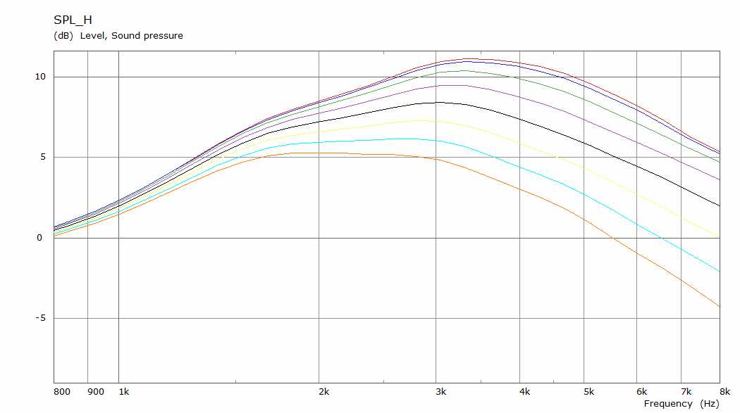
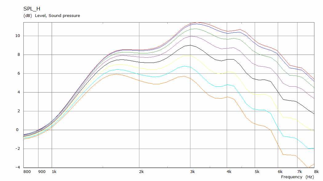
I then measured the on-axis response of the tweeter with the disk and without the disk. I was very careful to maintain mic position and test conditions between the two tests. In my plot I show the two measured responses, with black being the covered mid-driver which simulates a flat baffle, and blue being the system in its natural state. I also plotted the uncovered mid-driver normalized to the flat baffle measurement. I was surprised by the differences. The warbles between 3 – 6 kHz are present in both curves, but are more pronounced in the blue curve (uncovered mid-driver). But I was not expecting to see so much response differences at lower frequencies. From 900 Hz to 3 kHz, the effect of the uncovered mid-driver on the tweeter is +1.5 / -2 dB.
So I did not discover the cause of the 3k-6k warble, but I did find something interesting. I remember reading about this phenomenon either in a paper or in a book, but I don’t remember the details, and I believe it was a qualitative rather than quantitative assessment.
j.
After building and testing the system, I found some small diffraction effects which were not predicted by simulation. These small +/- 1 dB warbles are in the 3 kHz – 6 kHz range. When I compared this to the previous mid-HF satellites (built in 2020 New active 3-Way, Hypex and SB ), I found the same differences between simulation and measurement. Now remember these are two different tweeters (Satori TW29TXN-B in the first case and SB26CDC-C000-4 in the second case)
I suspected that the culprit was the cavity formed by the 6” mid driver. The simulation of the tweeter in the baffle assumes the baffle is flat. Even when two drivers are simulated, the simulation accounts for the acoustical interference between the two drivers, but not the shape of the drivers on the baffle. I show a screen shot of the baffle diffraction simulation for the tweeter.
To understand what is going on, I did an experiment with the older unit with the SB26CDC tweeter. I cut a circular disk of cardboard and covered the mid-driver, taping it in place. Using tape, I made the transition from baffle to cardboard disk as smooth and flat as possible. It was not perfect, and the disk protruded above the surface of the baffle by about 5mm, but the there were no sharp discontinuities.
I then measured the on-axis response of the tweeter with the disk and without the disk. I was very careful to maintain mic position and test conditions between the two tests. In my plot I show the two measured responses, with black being the covered mid-driver which simulates a flat baffle, and blue being the system in its natural state. I also plotted the uncovered mid-driver normalized to the flat baffle measurement. I was surprised by the differences. The warbles between 3 – 6 kHz are present in both curves, but are more pronounced in the blue curve (uncovered mid-driver). But I was not expecting to see so much response differences at lower frequencies. From 900 Hz to 3 kHz, the effect of the uncovered mid-driver on the tweeter is +1.5 / -2 dB.
So I did not discover the cause of the 3k-6k warble, but I did find something interesting. I remember reading about this phenomenon either in a paper or in a book, but I don’t remember the details, and I believe it was a qualitative rather than quantitative assessment.
j.
Attachments


Last edited:
These are just some random thoughts. Even though the midrange driver cone cavity affects the frequency response at the location of the test microphone, its impact on the system power response is likely much lower. Move the test microphone by the width of your head and see what that does to frequency response.
We almost never listen at the single point in space that a loudspeaker is tested at, and even if we tried there is only space for one of our ears at a time to be in that spot. But that isn't nearly as important as the emphasis that seems to be given to that magic point in space. I have always had equal concern for the system total power response, which is best measured in an echo chamber, because the space we listen in are actually something in between anechoic and totally echoic, even outdoors.
We almost never listen at the single point in space that a loudspeaker is tested at, and even if we tried there is only space for one of our ears at a time to be in that spot. But that isn't nearly as important as the emphasis that seems to be given to that magic point in space. I have always had equal concern for the system total power response, which is best measured in an echo chamber, because the space we listen in are actually something in between anechoic and totally echoic, even outdoors.
See p. 23 here for some examples.
https://pearl-hifi.com/06_Lit_Archi...ec_51/4445_Acoustical_Engineering_3rd_Edn.pdf
https://pearl-hifi.com/06_Lit_Archi...ec_51/4445_Acoustical_Engineering_3rd_Edn.pdf
Last edited:
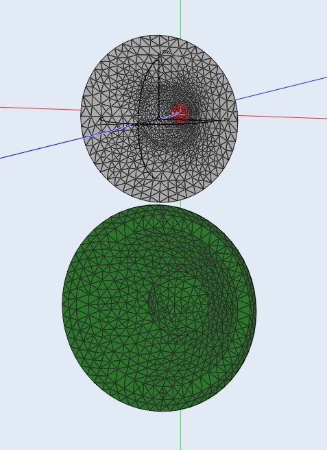
I ran some simulations before to see the effect of a woofer cone placed below a waveguide. Looks very similar to your measured results. A dip from the cone cavity and a ripple overall.
Waveguide alone in an infinite baffle
Woofer added below
Waveguide alone in an infinite baffle
Woofer added below
Fluid, is the sim on infinite baffle? I wonder how a freestanding waveguide with the good mouth rollback performs with woofer(box) below?

Fluid - Thanks for adding those sims. It answers a question I was pondering... if I would see the same kind of response if I was using a waveguide on the tweeter. Answer is probably yes.
Is this effect audible? Maybe. I measured an octave-wide dip of -2 dB from 800 to 1600 Hz, and a 1/2 octave peak of 1.5 dB from 1600 to 2200 Hz. I also checked back to the horizontal polar measurements I made of this speaker a year ago, and the effect from 800 - 1600 is present off-axis until 60 degrees. So it might be audible, but just barely audible.
Is it important ? Yes I think so. Anytime measurement differs from simulation, we need to understand why.
Last edited:
I think it really depends. For example, would you get a benefit from rounding the back corners of a cabinet? After all, the baffle has already eclipsed the driver from the point of view of any wave travelling down the side of the box, yet there is evidence of minor effects sometimes.. it depends on circumstances.
That sim is on an infinite baffle but the answer to your other question is here 2 way waveguide speaker build ABEC modelling you must have missed it 😉Fluid, is the sim on infinite baffle? I wonder how a freestanding waveguide with the good mouth rollback performs with woofer(box) below?
I doubt it, lots of felt is quite reflective and could cause more harm that it solves.Curious if a piece of felt might improve the response.
It could, but carefully applied? I'm imagining it could create a little diffraction but potentially save a lot. Basically we're just talking about directing things.lots of felt is quite reflective and could cause more harm that it solves.
A directive shape that is optimized for the application can indeed offer an improvement. The image shown was in effect a reflective step placed between the drivers and that is often a bad idea.It could, but carefully applied? I'm imagining it could create a little diffraction but potentially save a lot. Basically we're just talking about directing things.
Here is something that does simulate better vertically, in the model with the lip there is a small horizontal step which alters the horizontal a little above 5K so that is not quite apples to apples but it does show the effect of small changes in geometry at high frequencies.
Last edited:
That sim is on an infinite baffle but the answer to your other question is here 2 way waveguide speaker build ABEC modelling you must have missed it 😉
I doubt it, lots of felt is quite reflective and could cause more harm that it solves.
Ah yes thanks, I have missed it or just didn't remember anymore 😀 cool, not as big of an effect with the freestanding waveguide and rollback
Killer thread!!
The other day I stumbled across a paper that reminded me of this thread.
"Effects of the Cone and Edge on the Acoustic Characteristics of a Cone Loudspeaker"
Effects of the Cone and Edge on the Acoustic Characteristics of a Cone Loudspeaker
The part at "4.7. Impact of the Edge on the Acoustic Characteristics of the Loudspeaker" is what I find interesting.
It is so crazy what a little lump on a baffle can do. Can it be heard is my next question.
That sim is on an infinite baffle but the answer to your other question is here 2 way waveguide speaker build ABEC modelling you must have missed it 😉
I doubt it, lots of felt is quite reflective and could cause more harm that it solves.
I would experiment with felt. You'll be surprised how well it works if strategically applied. I had similar diffraction issues on a few small 2 ways. This appears to be a common issue with deep coned LF drivers. I've seen some significant improvements placing 3/8" thick strips of wool felt between LF and HF drivers. Don't use synthetic felt as its inferior to sheeps wool. A grille will also affect things and I always include it when making final crossover adjustments.
Bringing an old thread back to life...
Anyone have any absorption data for felt, particularly wool felt? I would also be interested in links to industrial grade acoustical or NVH felt.
I doubt it, lots of felt is quite reflective and could cause more harm that it solves.
I would experiment with felt. You'll be surprised how well it works if strategically applied. I had similar diffraction issues on a few small 2 ways. This appears to be a common issue with deep coned LF drivers. I've seen some significant improvements placing 3/8" thick strips of wool felt between LF and HF drivers. Don't use synthetic felt as its inferior to sheeps wool.
Anyone have any absorption data for felt, particularly wool felt? I would also be interested in links to industrial grade acoustical or NVH felt.
I've found absorption data for various materials by looking up some commercial products and their datasheets. And for some reason my phone copy/paste doesn't work so cant paste links 😀 Search for wool felt acoustic panel or something like that and you should find some.
Over here a supplier sells 15mm thick melanin absorption (flamex). I’d pick that any time above felt.
Here is something that is a bit interesting: When I designed the mid-HF satellites of my 3-way system, I modelled the diffraction of the mid driver and the tweeter with VituixCad2. These were built earlier this year https://www.diyaudio.com/forums/multi-way/366347-active-satori-textreme-9.html#post6523706...
So I did not discover the cause of the 3k-6k warble, but I did find something interesting. I remember reading about this phenomenon either in a paper or in a book, but I don’t remember the details, and I believe it was a qualitative rather than quantitative assessment.
j.
I suggest you to check it at different angles let's say up to 30° if the warbles remain
- Home
- Loudspeakers
- Multi-Way
- Interesting Diffraction Effect