Let's say I want to mount a capacitor that's too big to fit on a board as located. Or I need to mount a transistor on a heatsink but it's not convenient to mount the board it's self there. Is it ok to extend the leads of the component with wire so the the PCB and part don't have to be located together?
depends on the frequency and components you are dealing with, as (long) wires introduce additional inductance, capacitance and resistance.
so, if you add thin long wires to a 0,1 ohm resistor its value will change significantly.
so, if you add thin long wires to a 0,1 ohm resistor its value will change significantly.
Last edited:
Typically if you do this you might have to consider mechanical support and the risk of vibration over time - a component that's not flush and tight to the PCB surface can lead to failure over time. But the electrons generally don't care unless you are up in the RF regime where the extra stray inductance is a big deal.
Just a thought,
Use some of the same type of lead material to extend the connection. A bit difficult to do but possible, keeping extension to a minimum of course.
Use some of the same type of lead material to extend the connection. A bit difficult to do but possible, keeping extension to a minimum of course.
It's even acceptable not to use a PCB at all and chassis-mount everything, as was done before PCBs were invented 😉
Whether it will work well, poorly or not at all depends on the circuit and how much you need to extend the wires. For example, DACs will typically be more critical than main amplifiers, phono preamplifiers with 60 MHz op-amps may be more critical than those with 10 MHz op-amps. It's good to try to keep the extra wiring short.
Whether it will work well, poorly or not at all depends on the circuit and how much you need to extend the wires. For example, DACs will typically be more critical than main amplifiers, phono preamplifiers with 60 MHz op-amps may be more critical than those with 10 MHz op-amps. It's good to try to keep the extra wiring short.
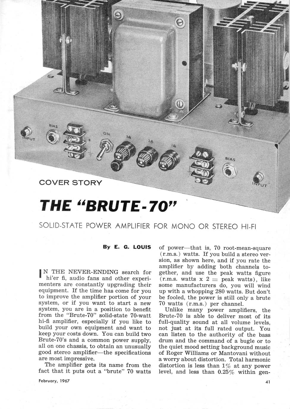
Just for comparison: in "the old days" , think 60´s and 70´s , it was normal to build "most" of an amp on a PCB but TO3 power transistors were on a finned heatsink some 2" to 6" away, and big supply caps were chassis mounted on their own clamps, again with 2" to 6" wires .... and amps worked fine.
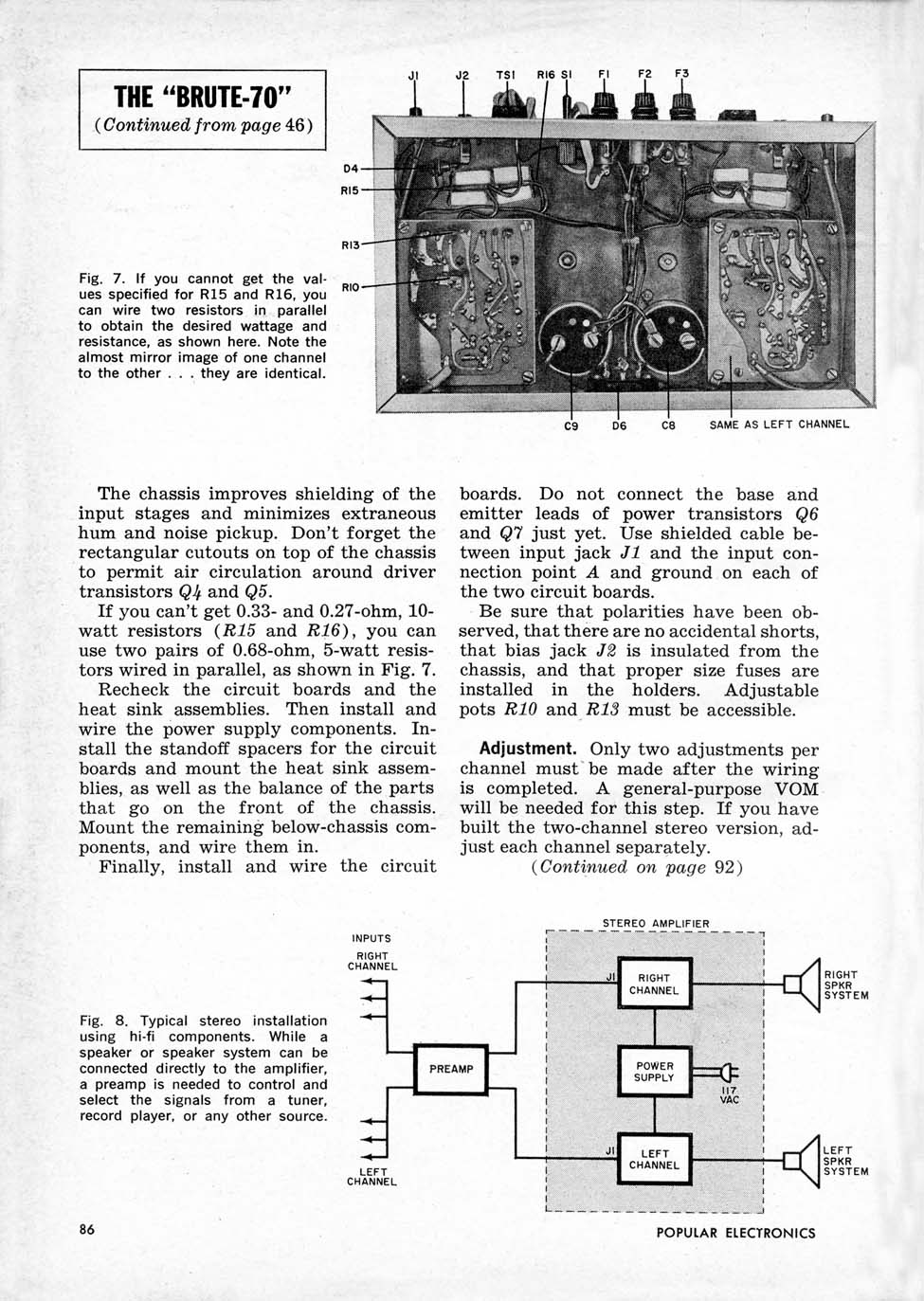
70´s 80´s Randall Guitar amplifier, notice chassis mounted TO3 power transistors (to boot, in sockets), pots, big filter caps on the chassis underside, hidden by the main PCB, ALL connected with reasonable length "flying" wires:

70´s 80´s Randall Guitar amplifier, notice chassis mounted TO3 power transistors (to boot, in sockets), pots, big filter caps on the chassis underside, hidden by the main PCB, ALL connected with reasonable length "flying" wires:
What I do, and let us be clear, I am NOT an expert, is to either use a tag strip at the point where I need to extend the lead or this:

I take a piece of Teflon insulated wire of about twice the diameter of the leads combined and then form a small coil of bare wire around the "mandrel". It slides easily off the Teflon insulation and then on to the two overlapping leads. A little solder and you have an incredibly strong joint. You can make it a little loose and tighten it up before soldering. The Teflon wire is just because I have a huge assortment in all diameters.
I got this suggestion from someone here so I can't take credit.
https://www.diyaudio.com/forums/tubes-valves/71300-photo-gallery-1005.html#post6464177
Last edited:
It is easier than it looks. Just wrap it as neatly as you care and then you can tighten it up a bit after placing it on the combined leads. I happen to use 24g silver wire as it is what I have in bare form. The pictures in the post show a nicer job than I did.
- Home
- Design & Build
- Construction Tips
- Is it ok to extend component leads with wire when facing placement constraints?