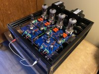
you're looking at the rear of the front fascia. so the transformers are mounted vertically. I am trying to move it away as far as possible from the amp circuit.
so the layout goes like
feedback/thoughts/suggestions?
Thank you.
EDIT: how about mounting to the sides of the chassis instead? the transformer will be at least 6-8inches (or 150-200mm if you're using metric) away from the amp circuit.

so the layout goes like
- transformers in front (mounted to the front fascia vertically)
- amp circuit in the rear and on the sides
- power supply in the rear and in the middle
feedback/thoughts/suggestions?
Thank you.
EDIT: how about mounting to the sides of the chassis instead? the transformer will be at least 6-8inches (or 150-200mm if you're using metric) away from the amp circuit.
Last edited:
There will be some magnetic interaction as the fields are pointing the same direction. How much depends on how big and how close they are. To avoid interaction they need to be at 90 degrees to each other. Not really convenient or practical in a normal case. If you have enough depth to put them like this \/ with 90 degrees in the v it would be better.

There will be some magnetic interaction as the fields are pointing the same direction. How much depends on how big and how close they are. To avoid interaction they need to be at 90 degrees to each other. Not really convenient or practical in a normal case. If you have enough depth to put them like this \/ with 90 degrees in the v it would be better.
what's a " \/ "? is that a bracket?
It’s supposed to be the relative position of the toroids. Only use a 90 degree angle between them to avoid magnetic field interactions.
how about mounting to the sides of the chassis instead? the transformer will be at least 6-8inches (or 150-200mm) if you're using metric) away from the amp circuit.
I don't think your proposed mounting arrangement shown in post #1 is a problem. There are many dual mono amplifiers that have two toroidal transformers mounted side by side on the chassis bottom plate. You have just moved the transformers to the front plate. Transformer interaction is still the same.
BugAmps GU50 PP uses this principle of mounting the toroidal transformers to the side of the chassis…you're looking at the rear of the front fascia. so the transformers are mounted vertically. I am trying to move it away as far as possible from the amp circuit.
so the layout goes like
- transformers in front (mounted to the front fascia vertically)
- amp circuit in the rear and on the sides
- power supply in the rear and in the middle
feedback/thoughts/suggestions?
Thank you.
EDIT: how about mounting to the sides of the chassis instead? the transformer will be at least 6-8inches (or 150-200mm if you're using metric) away from the amp circuit.
View attachment 1105963
I assume that they know what they are doing. First picture, the other pictures are from my rebuild. I use a stacked approach. That thing is a monster, lol
Attachments


That is how I do mine. I also use some copper RF shielding. I used heavy duty aluminum L brackets to mount then with. It’s a big mess right now due to testing mods and I’ll clean up when I’m happy!


The 90 degree mounting thing is something that should be considered when dealing with simple solenoidal windings like air core inductors. They can communicate to other solenoids if the fields bridge the windings.
Toroidal transformers keep the major flux lines within the winding cross section. Fields outside the windings will be confined to stray parasitic flux. For AC inputs, that is far far lower than the field within the toroid.
It might be possible to measure some interaction between cores, however, remember that they feed low pass filters that store lots of energy. I do not believe line-in toroids are that critical w/r to mounting concerns.
I would be far more concerned with the grounding. The signal reference is far more important.
John
I would be far more concerned with the grounding. The signal reference is far more important.
John
do you mean grounding the chassis to earth? or do you mean power supply ground?
Within the chassis grounding. The amplifier is designed to amplify the input signal with respect to its input ground (single ended input). If the chassis ground reference is affected by currents or stray magnetic fields, the amp will not know if it's actual signal or not.do you mean grounding the chassis to earth? or do you mean power supply ground?
There are no reasonable circumstances where any audio equipment should be connected to the earth, a huge no-no. The large loop formed by the AC power conductors back to the load panel, and the path an "extra" connection to earth takes forms a huge loop. Near strikes or even cloud to cloud bolts can generate significant voltages around that loop.
A tree across the street got tapped during a thunderstorm, and took out two items in my house, a dvd player and a smoke detector.
The cable run went up the side of the house directy above the meter pan, but the AC feed for the DVD started at the load panel, crossed the basement ceiling, then up the wall to the outlet that feeds the DVD player. That loop was roughly 30 feet by 20 feet, and I calculated worst case induction voltage as 400 volts per square meter. The plane of the loop wasn't in the same plane as the tree, So the effect will drop as cosine theta, theta being the off plane angle of the source to loop. And there will be some falloff as the back leg of the loop is roughly 50% further away, so trapped flux in the return will drop the induced voltage per square meter. But given the large loop and rapid rate of change of the magnetic field, it's easy to see how the effect can really get bad.
That is why I always recommend a multiport SPD, so the cable will be grounded at the outlet.
John
I can't conceptually think why 90 degrees is some magic number both in terms of interaction between the transformers or interaction with the circuits they power. If I really wanted to hurt my head I would forget about interaction between the transformers and concentrate on how the stray fields might influence the powered circuits and then tentatively dream about some sort of humbucking arrangement where the primaries are connected in anti-phase to try to cancel the far field influence. If you really want to go the full banana then try out https://www.femm.info/wiki/HomePage to model the possibilities. It may take a bit of thought to learn it and then work out how to model what you think you want but it will tell you what you think you need to know.
Oh. The previous might be a partial flight of fantasy because FEMM models in 2D and that might make a definition of the problem harder. Have a think about it though.
apologies for bringing back an old thread (as it's only now that I have time to assemble everything. what's an SPD? Thank you.That is why I always recommend a multiport SPD, so the cable will be grounded at the outlet.
John
I've stacked PSU toroids and mounted them next to each other. I've mounted toroid chokes right next to each other (each oriented identically along a plane). Have never observed any issues and have always had dead silent equipment. I've also mounted an SMPS transformer pretty close (1-2") from a toroidal choke AND a PSU choke and did not observe any issues. Admittedly I do not have an oscilloscope and was satisfied with placing my ear next to 98 dB sensitivity speakers with maximum volume, so cannot provide any measurements for these scenarios.
Once I did observe that running wiring for an amplifier power switch BEHIND the two chokes had the potential to inject a lot of noise into the amplifier. In particular, noise from an AC dimmer switch.
Once I did observe that running wiring for an amplifier power switch BEHIND the two chokes had the potential to inject a lot of noise into the amplifier. In particular, noise from an AC dimmer switch.
Nah, these are toroidals, they won't interact worth speaking of. Normally you'd stack them vertically and use one long mounting bolt. If they are mains power the interaction isn't relevant either. If one is a signal transformer and the other mains, that might be a worry as they do have a little amount of stray field.There will be some magnetic interaction as the fields are pointing the same direction. How much depends on how big and how close they are. To avoid interaction they need to be at 90 degrees to each other. Not really convenient or practical in a normal case. If you have enough depth to put them like this \/ with 90 degrees in the v it would be better.
- Home
- Amplifiers
- Power Supplies
- Is it ok to mount 2 toroidal transformers in this fashion? (image inside)