I hope you all don't mind if I post something that's purely theoretical. I'm afraid I love line arrays but may never actually get to build one. I've been thinking about the subject of line sources for a while and recently stumbled upon a new (to me) waveguide from JBL that has me thinking about them all over again.
The ideal line source is a single long and skinny array which also goes down to at least 200 Hz or lower. The problem we are faced with is often getting enough bass vs. getting acceptable horizontal dispersion. Long ago I ran into flat ESL speakers which were about 8" wide which sounded great in exactly 1 location in the room. I then often wondered if there was any way of putting a "spoiler" of sorts in front of them to widen the dispersion. Same kind of issue applies to line arrays made from 4" circular drivers. They get deep enough but eventually beam around 4-5 kHz.
Then I saw these JBL speakers with a waveguide that improved the off-axis performance of an otherwise too wide a woofer and I wondered: Is it possible to build a line source out of 4" drivers with a similar idea? If so, is it something that would even apply to a flat ESL design?
Probably, but the "waveguide" for the 4" driver will introduce cancellations that may be in the intended pass band.Is it possible to build a line source out of 4" drivers
Isn't that to match DI with the horn and help control over a limited bandwidth? With a 4" drivers the DI is so different vs 15 match to say a 1"?
Typically doesn't the waveguide end up on the 1" I am thinking Revel as an example.
How do you want to use it?
Rob 🙂
Typically doesn't the waveguide end up on the 1" I am thinking Revel as an example.
How do you want to use it?
Rob 🙂

Would the conclusion that bigger is better for vertical and smaller is better for horizontal be standing in the way at all?
Would the conclusion that bigger is better for vertical and smaller is better for horizontal be standing in the way at all?
Not sure what you mean? I see it as a refinement of the basic wave guide aperture optimized for a larger driver. Take a look at a pth1010 with no lobes up top.
You have the familiar pinch and wide open vertical.
Attachments


The better answer is a line of planar tweeters crossed at 4K to your proposed 4” woofers. The GRS slim 8” planar tweeter fits the bill as does the Dayton PT 2c. You could also use a line of 3/4” domes like the Dayton ND20- fb……inch for inch, the domes are actually cheaper in quantity and have MUCH BETTER off axis response than just about anything .I hope you all don't mind if I post something that's purely theoretical. I'm afraid I love line arrays but may never actually get to build one. I've been thinking about the subject of line sources for a while and recently stumbled upon a new (to me) waveguide from JBL that has me thinking about them all over again.
The ideal line source is a single long and skinny array which also goes down to at least 200 Hz or lower. The problem we are faced with is often getting enough bass vs. getting acceptable horizontal dispersion. Long ago I ran into flat ESL speakers which were about 8" wide which sounded great in exactly 1 location in the room. I then often wondered if there was any way of putting a "spoiler" of sorts in front of them to widen the dispersion. Same kind of issue applies to line arrays made from 4" circular drivers. They get deep enough but eventually beam around 4-5 kHz.
Then I saw these JBL speakers with a waveguide that improved the off-axis performance of an otherwise too wide a woofer and I wondered: Is it possible to build a line source out of 4" drivers with a similar idea? If so, is it something that would even apply to a flat ESL design?
View attachment 1338986
A line array appears to be either a 2d solution to a 3d problem, or appears to be showing a stark contrast in V vs H needs. My question to Erik would be that if a finite horizontal width problematically reduces the listening spot, why use a long line vertically? Is there more to it?Not sure what you mean?
Do you have any more information on how this is so?I see it as a refinement of the basic wave guide aperture optimized for a larger driver.
Is it possible to build a line source out of 4" drivers with a similar idea?
It's kind of possible. There are several issues. While it's easy to narrow the exit from the driver in one plane to get wide dispersion, making it uniform in the other plane so you can form a line source using multiple adjacent drivers that sum coherently is more difficult the higher you try to go in frequency. I used a lot of FEA when working on this issue in systems I worked on. Next, you usually get the power response of the driver after putting a structure in front of it to change the directivity as discussed, so if you use a larger driver it's going to typically start rolling off at a lower frequency. So trying to make something extend high in frequency with a 4" driver might be difficult. Designing for smooth frequency response at high frequencies also becomes harder the more you try to extend a driver's bandwidth. Also, at least in the array's I worked on, the array gain effect of having multiple drivers decreases as you go up in frequency making getting enough output at higher frequencies more challenging. Last, if you have a very restrictive design to get your desired directivity, you can run into issues with air velocity at low frequencies. A multiway system is the obvious solution to most of these problems.
Do you have any more information on how this is so?
I have to go looking I remember that 15's lense being discussed somewhere. I would be great if we had spinarama on the system with and without to see exactly what its doing. If I can find it will post it.
OK found it not much here but it is mentioned. And a little bit more in the brochure. No specifics
https://pro.harman.com/insights/har...e-principal-jbl-loudspeaker-systems-engineer/
Rob 🙂
Attachments
Last edited:
An axisymmetrical waveguide suits an open woofer. This pinching technique is not there to fix a problem with that, it's only used to get 90x60.not much here
Is 90x60 necessary? Perhaps not if you use a ceiling cloud... It does create the compromise that 60 degrees is harder to hold, and as a result the vertical should be taller than the horizontal.. but it is actually shorter than the woofer.
Perhaps some juggling found a workable cross, but does that teach us anything today?
X An axisymmetrical waveguide suits an open woofer. This pinching technique is not there to fix a problem with that, it's only used to get 90x60.
Axisymetrical why have a waveguide at all? Just match it up top which is the norm on the Horizontal and aim the lobes out of the listening window. Well if your design goal is 90 x 60 it works. It seems to match in both H and V so curious where the lobes appear.
Is 90x60 necessary? Perhaps not if you use a ceiling cloud... It does create the compromise that 60 degrees is harder to hold, and as a result the vertical should be taller than the horizontal.. but it is actually shorter than the woofer.
Hmm a bit confused here. That's typical where you have a narrow V compared to H. My personal preference is 100 X 100 but that's me.
Perhaps some juggling found a workable cross, but does that teach us anything today?
I think so you can take a cone driver and use a tailored aperture to control directivity. This basically with a plate without a horn. So yes I think it's a gain. This aperture has no real depth beyond the frame. So you are saving both space and weight compared to an equivalent horn solution that matches that directivity over the frequencies where it is implemented.
YMMV
Rob 🙂
Last edited:
Kind of what Presonus made here ?The better answer is a line of planar tweeters crossed at 4K to your proposed 4” woofers. The GRS slim 8” planar tweeter fits the bill as does the Dayton PT 2c. You could also use a line of 3/4” domes like the Dayton ND20- fb……inch for inch, the domes are actually cheaper in quantity and have MUCH BETTER off axis response than just about anything .
Yes, 90x60 is not as simple as it seems - https://www.diyaudio.com/community/threads/is-it-best-to-use-a-non-axisymmetric-waveguide.375799/Hmm a bit confused here. That's typical where you have a narrow V compared to H. My personal preference is 100 X 100 but that's me.
Why have a waveguide at all? Is that the question you intended to ask?Axisymetrical why have a waveguide at all?
Presonus uses wide range drivers instead of tweeters and crosses much lower……same principle though….still a line array since the wide range are aligned in a vertical line. Off axis response is likely very poor above 10khz though…..but that’s just fine for commercial sound reproduction.Kind of what Presonus made here ?
View attachment 1339126
My suggestion since the OP was talking about 4” woofers would be those in a vertical line along side a vertical line of tweeters….planars or domes.
Now as to the length of the line…….there’s a LOT of misconceptions and misinformation out there……..lots of talk of lines that go from the floor to the ceiling…….the intended purpose is to narrow the vertical directivity to reduce floor and ceiling bounce. And for folks using small wide range for the woofers…..like 4” and less……the complimentary purpose is power handling and low frequency response. But here‘s the problem….. multiple sources produce lobes and combing. Using the most critical frequency of 1khz and the length of the line drivers playing at 1k, IDEALLY you’d want 10x the length of the line to the listening position for proper summing and the intended behavior of a line source, or far field. That’s not really feasible for us as home users, so the next best is mid field or 5x the length of the line…….sounds pretty good and consistent when you listen within the physical vertical axis ( a little more than the length of the line) and the off axis horizontal if designed properly should be very good out to +/- 60 degrees.
All of the above is my way of saying that if you design a line source properly, you DO NOT need or want too long of a line………seated ear heigh of around 36” and standing average around 72” gives you a desired line height of 36” give or take.
Last edited:
Thoughts:
1) The dude who designed it is the same dude who made the waveguide for the JBL M2 (Charles Sprinkle.) He's fairly active on Facebook groups dedicated to audio; he might just answer any questions you ask. He is no longer with JBL, he founded Kali Audio.
2) That's not a waveguide, it's a diffraction slot
3) Kef did the same thing with some of their speakers in the 70s
4) There was a dude who used to compete with a car that had a setup like this. "Douglas Button" I think? IIRC, he was at JBL also. (No longer.) There are discussions of it over at DIYMA and even going back 20+ years on some now defunct car audio forums.
As I understand it, the technology is straightforward. The diffraction slot simply makes the woofer behave as if it's smaller than it actually is. For instance, a cone that's 13.5" in diameter will begin to beam at 1000Hz. (Speed of sound / diameter)
This can be problematic, depending on the xover frequency and beamwidth of the waveguide. In particular, if the waveguide has especially broad coverage, there may be a directivity mismatch in the midrange. (Never a good thing.)
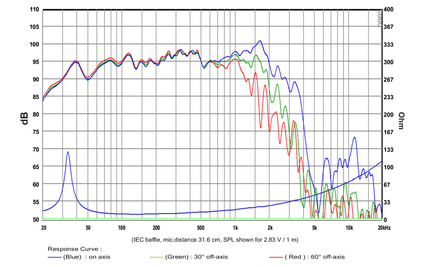
For instance, in this measurement of an inexpensive prosound woofer from SB Acoustics, you can see that it will do fine with a crossover of about 1000-1350Hz, but if you go higher than that, the directivity of the woofer is quite narrow.
So the diffraction slot is there to improve that. I imagine it may also be there to do some acoustic filtering; basically a piece of plastic costs about a dollar while a high power inductor can cost $15 or more, so the lens may be a way to save money on the xover too.
Note that this situation is the reason that the Gedlee Summa (which used to be my reference speaker) uses such a low xover point. IIRC, it's something like 700Hz. Which wouldn't be acceptable for a high power prosound speaker, but is fine for listening at home.
1) The dude who designed it is the same dude who made the waveguide for the JBL M2 (Charles Sprinkle.) He's fairly active on Facebook groups dedicated to audio; he might just answer any questions you ask. He is no longer with JBL, he founded Kali Audio.
2) That's not a waveguide, it's a diffraction slot
3) Kef did the same thing with some of their speakers in the 70s
4) There was a dude who used to compete with a car that had a setup like this. "Douglas Button" I think? IIRC, he was at JBL also. (No longer.) There are discussions of it over at DIYMA and even going back 20+ years on some now defunct car audio forums.
As I understand it, the technology is straightforward. The diffraction slot simply makes the woofer behave as if it's smaller than it actually is. For instance, a cone that's 13.5" in diameter will begin to beam at 1000Hz. (Speed of sound / diameter)
This can be problematic, depending on the xover frequency and beamwidth of the waveguide. In particular, if the waveguide has especially broad coverage, there may be a directivity mismatch in the midrange. (Never a good thing.)
For instance, in this measurement of an inexpensive prosound woofer from SB Acoustics, you can see that it will do fine with a crossover of about 1000-1350Hz, but if you go higher than that, the directivity of the woofer is quite narrow.
So the diffraction slot is there to improve that. I imagine it may also be there to do some acoustic filtering; basically a piece of plastic costs about a dollar while a high power inductor can cost $15 or more, so the lens may be a way to save money on the xover too.
Note that this situation is the reason that the Gedlee Summa (which used to be my reference speaker) uses such a low xover point. IIRC, it's something like 700Hz. Which wouldn't be acceptable for a high power prosound speaker, but is fine for listening at home.
Last edited:
Ever get a chance to hear the Beveridge ESL's?Long ago I ran into flat ESL speakers which were about 8" wide which sounded great in exactly 1 location in the room. I then often wondered if there was any way of putting a "spoiler" of sorts in front of them to widen the dispersion.
Apologies for the confusion caused my my hypothetical musings.
We are getting into alternative designs from a single driver line array (LA). Not really my intention to discuss. I really just wondered whether we could take the idea of pinching the sides to improve horizontal dispersion. Also not interested in matching a horn in this case really. I am more curious about whether the 2 dimensional wave guide could be adapted to be a 1 dimensional case by ignoring the top and bottom portions of the JBL wave guide.
The 4" full-range driver is also, of course a compromise in that it will never have spectacularly smooth treble.
Never even heard of them. 🙂Ever get a chance to hear the Beveridge ESL's?
US Patent 3,668,335 by Harold N Beveridge
https://patents.google.com/patent/US3668335A/en
The electrostatic transducer is shown surrounded by an enclosure that has an outlet passage preferably significantly smaller than the transducer and an acoustic lens preferably guides the sound through the narrow outlet into a wave form of circular cross-section.
. . .
The lens is composed of a series of walls 20,, 20 ".20 (see FIG. 1a) which are straight in the vertical direction (see FIGS. 4 and 5) but are spaced apart and curved in accordance with a special pattern in the horizontal direction to define a series of channels (see FIGS. 1 and 1a). Thus outer wall 20 and the next adjacent wall 20 define a channel (channel I) having an inlet of width W, exposed to a corresponding outer portion of diaphragm 12 (through the apertures 16a of the outer electrode 16). The walls 20, and 20 converge together in the direction outwardly and simultaneously curve toward the centerline of the lens, to the lends throat region 20,.
Near this region the channels begin a re-entrant curve so that at the throat 20, the channel is again substantially perpendicular to the diaphragm, although displaced significantly toward the centerline. Beyond this region the walls 20, and 20 curve outwardly from the centerline and diverge from each other, terminating in ends 20e which, in this example, are disposed outside of the front wall 18a of enclosure 18. The axis A, of the outlet of channel 1 is thus directed outwardly at a substantial angle from its direction of the channel axis at the inlet. In like manner the other side of wall 20 and wall 20 define channel II. It is disposed to receive the sonic output of the next adjacent portion of the diaphragm. It curves and converges and diverges similarly to channel I while its output axis A is disposed at a lesser angle to the normal to the diaphragm. Channel II provides the next adjacent segment of the solid angle a achieved by the lens. Channel III is likewise defined by the walls 20 and 20,, and so on to Channel IX, along which extends the centerline. The lens structure is symmetrical about the centerline, and thus the right hand outer channel XVIII curves in like manner, but in opposite direction, to Channel I.
The outer portion of the walls 20, 20,,, are shaped to establish the series of outlet axes A, A,,.,, such that projections of these axes intersect at a common inward point C spaced substantially (eg 1 foot) from the diaphragm. Since a dispersed angle a of about one half a circle is desired for this embodiment center C lies on the plane projected through the front surface 18a of the enclosure. Preferably, as shown, the curvatures of the walls are arranged so that the sound path P along each of the channels and outwardly to a circle projected from the common center C of the outlets is the same length for all channels.
The effect of these features is to emit a circular wave front even though the sound emitting diaphragm is both planar and extremely directional for the high frequencies. With a suitable shaping of the walls, the wave form can be spherical, however in the preferred embodiment shown, the speaker retains the same circular horizontal cross-section throughout its height, hence the output sound wave is of cylindrical form
- Home
- Loudspeakers
- Multi-Way
- JBL - like waveguide for line arrays?