I just received a Juicy Music Blueberry Xtreme with Cream preamp recently. I originally owned it from 2007-2018, sold it, and just bought it back. It was "one that got away".
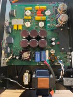
I opened it up to put tubes in and see that 2 traces to the rectifier bridge are lifting. The PCB looks like it took a lot of heat in the area of that bridge. The caps around the bridge also look to be cracked / drying out. Before I power it up I want to fix that up.
While I was waiting for the shipment I wanted to see about any mods or if technical details are out there on this preamp. I found out that Mark Deenen (designer/builder) offered a few mods that I'd like to implement: power supply mod, maxim mods, and 6H30 retrofit. Mark is long out of the business now. I tried using an email address I found for Mark D, but it bounced. I tried a call and email to Craig at NOS Valves. No response.
Does anyone have schematics for this one?? Does anyone have this preamp with those mods who would be willing to take a few close up pictures of the boards so I can compare things?
My plan is to simply put a bridge rectifier with a snubber circuit on the chassis and run wires where they need to go. That's an easy fix for the obvious issue, and it solves my short term need. I'll need more info to jump into the other mods.
Attachments

I'll post this one here for posterity.
I just wrapped up my mods. Mark D was on the Klipsch forum and provided schematics.
Added High Voltage Mod - Removed rectifier tube, added new solid state rectifier PCB with snubbers, inrush current limiters, bleeder resistor, and additional filtration. I tweaked values in the power supply resistors to match the voltages I measured before doing mods. Through some modeling and optimization (PSU Designer 2, build, measure, add to spreadsheet, calculate, tweak, repeat) I figured out the ideal new power supply resistor values for a 6DJ8/6922 in position V4 and for the 6H30.
Added Low Voltage Mod - Removed old bridge, added new bigger bridge/filter PCB with inrush current limiter, additional filtration. I updated the 10W CRCRC filter resistor values to spread the voltage drop before the regulator. This way the heat is spread around between 2 10W resistors and the regulator/heatsink. And the ripple is minimized before the regulator, giving it a cleaner signal to start with. I changed the to higher rated regulator heatsink. In hindsight, this was probably not necessary because the dissipation at the regulator is appx 5W with 1R2 10W resistors in LV supply.
Updated to 6H30 in position V4 including cathode bypass caps.
Added CL60 between IEC and Chassis Ground. This is a classic ground loop / hum breaker technique I learned building First Watt Clones.
It sounded great on the bench - now I need to get it into my real system!
Will it drive an F4??!?!!?
Attachments
-
 Juicy Blueberry HV Mod Schematic-1.0d.jpg298.2 KB · Views: 139
 -
 Juicy Blueberry LV Mod Schematic-1.0b.jpg294.3 KB · Views: 137
 -
 JuicyMusicBlueberry-Modded-01.jpg693.6 KB · Views: 133
 -
 JuicyMusicBlueberry-Modded-02.jpg647.4 KB · Views: 117
 -
 JuicyMusicBlueberry-Modded-03.jpg722.4 KB · Views: 110
 -
 JuicyMusicBlueberry-Modded-04.jpg643.6 KB · Views: 139
@rhthatcher
Wow. Absolutely stunning work; not only did you repair but you improved upon the original! It was obviously built to a price point and you took it to the next level.
Best,
Anand.
Wow. Absolutely stunning work; not only did you repair but you improved upon the original! It was obviously built to a price point and you took it to the next level.
Best,
Anand.

Thanks Anand! This is a killer sounding preamp from the start. These improvements will allow it to go the long haul.
Thankfully Mark (the man behind Juicy Music) recently shared the schematics for some of these great pieces. So they can be serviced for years to come. He has been retired a while.
Juicy was a one man operation. I don’t imagine that he made mega volume production, but he did make wonderful sounding gear with a huge “bang for the buck” factor. These have quite a following among the Klipsch community. My unit has mm and mc phono and linestage. And it goes into a really nice walnut outer chassis. It’s a beautiful preamp.
Question is…has he posted these schematics somewhere or is he willing to share it here on diyaudio in a public domain? There might be folks who want to clone one from the ground up and use it drive F4’s, Mofo’s, etc…Thanks Anand! This is a killer sounding preamp from the start. These improvements will allow it to go the long haul.
Thankfully Mark (the man behind Juicy Music) recently shared the schematics for some of these great pieces. So they can be serviced for years to come. He has been retired a while.
Juicy was a one man operation. I don’t imagine that he made mega volume production, but he did make wonderful sounding gear with a huge “bang for the buck” factor. These have quite a following among the Klipsch community. My unit has mm and mc phono and linestage. And it goes into a really nice walnut outer chassis. It’s a beautiful preamp.
Best,
Anand.
Good question!Question is…has he posted these schematics somewhere or is he willing to share it here on diyaudio in a public domain? There might be folks who want to clone one from the ground up and use it drive F4’s, Mofo’s, etc…
Best,
Anand.
There is a thread over in the Klipsch forum where Mark posted schematics.
https://community.klipsch.com/index.php?/topic/210979-maybe-you-have-a-juicy-question/page/7/
I stumbled across this since I have one of these sent to me for repairs and some modifications. One thing I noticed in the one I'm working on is that if you keep the 12X4 rectifier, pin 2 is connected to the power transformer instead of pin 1! So, it's only getting half wave rectification from the tube. I will replace the tube with the ST STPSC2H12 SiC rectifiers as they have no "reverse recovery" and 750 ohms in series with the transformer CT will give the same B+. For the filament supply, 0.62 ohms in series with the AC to the bridge rectifier lowers the heatsink temperature of the filament regulator by 15C (It was running at 114C). I am also eliminating the mica insulator as even that should take another ~4C off the regulator's case temperature. (I'm not worried about a live heatsink at 6.4V...) I decided on the resistor into the full wave bridge instead of after as it increases the conduction angle. The filter cap after is 4700uF. One more thing, this one has the remote option, they chose to use a 7805 off the 6.4V filament supply. One complaint was the remote wasn't working and found the 5V to be too low causing this, so an LM2940T-5 with proper decoupling will be going in it's place. One more thing... This one has the K&K constant current sources, a 5H choke in the B+ supply, and the 6H30pi.
-Sol Samet
-Sol Samet
- Home
- Amplifiers
- Tubes / Valves
- Juicy Music Blueberry Preamp - Tech Info?