I posted previously regarding bias and DC offset in this KA-7300. Other than the large 10,000mF electrolytic capacitors, all others (including 3 which were non-polarized) have been replaced. Also the original A750 transistors have been replaced with 2SA970. DC offset voltage is about 1/2 what is was when I started and is now hovering around 50mv.
I was just now preparing to re-assemble the amplifier and noticed that R1 and R2 were producing a fair bit of heat - 250F degrees & 215F degrees respectively. I measured voltage across them and both read a little more than than 20.5 volts.
Does that temperature seem a little too high?
It may or may not be relevant but the left channel heat sink is every so slightly warmer than the right one which is basically room temperature with the amp idling.
I came across an AK thread with posts by Echowars and it seems to address this very same high temp resistor issue:
Kenwood KA 7300 Power Supply | Audiokarma Home Audio Stereo Discussion Forums
I am prepared to follow suit with his recommendations to replace them both, upping R1 to 3W and replace the mentioned stock CZ-245 zener diodes (24.5V 2W) with new 1N5934B (24V 3W) - provided they are still available.
But since the amplifier discussed in that thread is a 220/240 volt version, will that change those substitutions if the amp is a North American model?
EDIT: I can get 1N5359B diodes locally - 24V 5W. Would those work?
Last edited:
It makes no difference as the mains transformer primary is the only difference. See the service manual for more information.
Just encountered another dilemma after re-assembling the amplifier - no sound. Reading what I could find about this situation in a Kenwood KA-7300 seems to say a good possibility is the relay driver transistor packed it in. There are two transistors on the board (and they don't correspond with the SM), a TO126 package and TO98-1. As my understanding is somewhat lacking, can someone advise which one is the relay driver?
I checked the TO128 in circuit which is a 2SC2566 and measured voltage where none should be. From what I could deduce, I can replace that one with a KSA1220YS and I've got a couple coming.
If it's the TO98-1 package (a 2SC1681), I've found little about it so don't know how to determine a suitable substitute.
I'm assuming a component failure rather than a mechanical relay failure because tbe amp did produce sound at least with headphones. Now it's silent, not even a relay click.
Last edited:
Hi 62vauxhall,
There are times when you tread where you ought not to tread. I'd say you're in the middle of that.
Don't expect to read threads and get accurate answers every time. There is a lot of nonsense posted everywhere by folks who don't know what they don't know. Some times you need a real technician to help you out.
So. Do you like this amplifier? You want to keep it in a running state? Do you have the equipment and experience for this, or did you just read about it?
I don't think that transistor packed it in. You might have an active protection circuit. Measure the output voltages before the relay. By the way, 50 mV DC offset isn't very good. You haven't matched the input transistors, that much is obvious.
What's your next move?
-Chris
What is the resistance of the hot resistors? Divide the voltage across them with the resistance value. Take the value you get and multiply it with the voltage - now you have the wattage these resistors are dissipating. If it is higher than the resistor type max, you obviously have something shorted down the line.
My next move was pulling that transistor and you were right, it seems fine.
*I did not match those pairs carefully. I used the same method as I had previously but I guess I was lucky then.
*I do not know exactly where to take the "voltage before the relay" measurement you mention.
*I like the amplifier just fine, it reminds me of the Model 600 I owned for 28 years. Had to sell that when I was laid off and unemployed for a year, my savings and some possessions all went bye bye. Nasty thing to happen when over 60 and your area of expertise becomes obsolete. Besides, if I did not take the amp, it was going in the garbage.
*I have no equipment other than a DMM. I'd like an oscilloscope but unfortunately my present income prohibits the expense and I have yet to find a free one.
*My only experience thus far had been a few preamps and some 8 track decks. Those involved nothing more than replacing of old capacitors and a few other things.
*Yes to "just reading about it". So far, I was able to receive answers to questions by reading forum posts and from posting myself.
*I suppose you are right too about self styled experts. Since you are a moderator on this site, I guess you've seen your fair share.
Last edited:
Hi again. I questioned the parts store vendor about operating temperature. He said these resistors, both existing and new, were in the 220+ Celsius area. Since the measured temperature was 250 Fahrenheit, they seem to be within operational range. I will do as you suggest when I get home tonight and see what I come up with but from the looks of the board in the immediate area and the resistor's leads, things have been toasty warm there a long time.What is the resistance of the hot resistors? Divide the voltage across them with the resistance value. Take the value you get and multiply it with the voltage - now you have the wattage these resistors are dissipating. If it is higher than the resistor type max, you obviously have something shorted down the line.
Hi 62vauxhall,
Ignore the moderator tag. I'm just a member like everyone else, except moderators have extra work to do. It's a hard working group that make up the moderating team.
Okay, now I have a good picture of your situation. I'm sorry to hear of your predicament. I hope it resolves in a more positive way for you.
Find the emitter resistors and measure the voltages there in relation to the chassis & report back please.
Where are you located roughly? Canada is a really large place. Hopefully someone closer to you can lend a hand. This web site is pretty good, but since every situation is a little different, you have to ask directly about your own equipment. Some of your answers will be more accurate than others. You've been a member long enough to maybe have determined which members can give you the best advice. There are many here you could listen to and be okay. Then, there are the others ...
-Chris
What is the resistance of the hot resistors? Divide the voltage across them with the resistance value. Take the value you get and multiply it with the voltage - now you have the wattage these resistors are dissipating. If it is higher than the resistor type max, you obviously have something shorted down the line.
It should be good then. The 180 ohm resistors's 20 volts calculates to 2.1 watts - there was a 2 watt there originally. The 270 ohm's 21 volts is 1.6 watts and it was formerly a 3 watt. There are larger wattage ones in their place now.
I thought I was buying a 3 watt & 5 watt replacement but I guess one package was mislabeled because both resistors themselves are marked as 5 watt.
Hi 62vauxhall,
Ignore the moderator tag. I'm just a member like everyone else, except moderators have extra work to do. It's a hard working group that make up the moderating team.
Okay, now I have a good picture of your situation. I'm sorry to hear of your predicament. I hope it resolves in a more positive way for you.
Find the emitter resistors and measure the voltages there in relation to the chassis & report back please.
Where are you located roughly? Canada is a really large place. Hopefully someone closer to you can lend a hand. This web site is pretty good, but since every situation is a little different, you have to ask directly about your own equipment. Some of your answers will be more accurate than others. You've been a member long enough to maybe have determined which members can give you the best advice. There are many here you could listen to and be okay. Then, there are the others ...
-Chris
I just took those readings and the TO96-1's emitter resistor to ground is 9.1 volts and the TO126's - 2.5 volts.
I am located in Surrey, BC - pretty much across the Fraser River from Vancouver.
Yes, there are posters to whom I pay attention, those frequently cited by other forum members. I am actually quite pleased when one of them responds to something I've thrown out there.
Hi 62vauxhall,
I'm sure there are couple members close to you that could give you a hand.
-Chris
I'm sure there are couple members close to you that could give you a hand.
If you have 2.5 volts on the emitters of the output devices, your amp is in protect mode. The relay will not close under those circumstances. Did you mean TO-126 (smaller rectangular part) or a TO-3 / TO-204 (metal part with screws at each end, oval shape) or one of the many plastic equivalents (TO-3P, TO-264 I think, etc ...)and the TO126's - 2.5 volts.
-Chris
Yes, TO126. Rectangular as you say with a hole through near the top. I'd attach a photo but I won't be home for another 12 hours.
With regard to those "other posters" it was one who goes by Echowars that cited this transistor as the possible culprit in keeping the relay from closing. Considering that their familiarity with this amp (perhaps Kenwood in general) on that other site (AK) was acknowledged, I took notice of what was said. Could be wrong but I believe Echowars has contributed to this site as well?
BTW, my situation which you said you hoped would change did somewhat. It went from a 5 day 40 hour week to 87 hours spanning 6. Still only earn about 3/4 of the former wage and no medical/dental or paid time off. That's why I shall not be home for a while.
Hi 62vauxhall,
Is this part an output transistor? If it is damaged, it most likely went short and would therefore cause a high amount of current flow. That doesn't match your symptoms. A lower DC offset without high current flow in the output stage would generally point to a problem in the voltage amplifier area, echos or no.
-Chris
No, not an output.
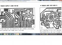
I understand it to be called a relay driver transistor and it's in the power supply section identified as Qk1. Please know that the number quoted on the diagram (2SD414) is not what is on the board which is a 2SC1567.
Same goes for Qk2. Not a 2SC1746 but a 2SC1681.
EDIT: Regarding the outputs, it uses power modules labeled Trio TA-80W.
Attachments

Last edited:
- Status
- Not open for further replies.
- Home
- Amplifiers
- Solid State
- Kenwood KA-7300 - temperature of power supply resistors