I have a Kenwood KA-8006.
Volume and general audio quality seems on the weak side, but I've never heard one before, so I have no point of comparison.
The right channel is weaker than the left.
DC Offset measured with amp warmed up, volume at min., no speakers connected, input selector on AUX 1 with nothing connected to it.
Right speaker terminals show -30.8mV,
Left speaker terminals show +24.2mV.
Bias measured (DC mV) at pins 8 and 5 on the main amp boards per advise I read on another forum - target should be 30mV.
Right Board was 13.0mV
Left Board was 21.2mV.
Any advice on where to start?
I have a Kenwood KA-8006. Bias should be 30mV. Right was 13.0mV Left was 21.2mV.
Look over the caps for bulges and replace the bad ones. Check the thermal paste on the output devices and replace it
and the insulators if dried out. Clean the controls and switches with contact cleaner. Burn it in for a day or two
if it hasn't been used much. Carefully adjust the bias in small increments to spec. If you like it now, you can do a
more complete restoration.
Download the free service after registration here: Kenwood KA-8006 Manual - Solid State Stereo Integrated Amplifier - HiFi Engine.... Any advice on where to start?
Look at the adjustment & troubleshooting guide P7 and find the bias adjustment pots. VRe1. Take care, it may be fragile.
If not already performed, a recapping, particularly of the main (yes, the big black ones) electrolytic caps. will be long overdue. Note:
1) cap sizes have shrunk dramatically over the last 40 years or so.
2) You can use larger values capacitance up to twice those specified, with few problems.
3) You can use higher voltage rating parts than specified but never lower.
4)The DC offset is not adjustable but it's fine as it is.
Last edited:
Download the free service after registration here: Kenwood KA-8006 Manual - Solid State Stereo Integrated Amplifier - HiFi Engine
Look at the adjustment & troubleshooting guide P7 and find the bias adjustment pots. VRe1. Take care, it may be fragile.
If not already performed, a recapping, particularly of the main (yes, the big black ones) electrolytic caps. will be long overdue. Note:
1) cap sizes have shrunk dramatically over the last 40 years or so.
2) You can use larger values capacitance up to twice those specified, with few problems.
3) You can use higher voltage rating parts than specified but never lower.
4)The DC offset is not adjustable but it's fine as it is.
I've heard that are some parts - in some specific models - that might be kept under same capacitance, i.e., voltage regulators, DC protection circuits, etc, (not sure if these apply for the KA-8006). Increasing capacitance in those parts would make some of them "sluggish", too slow to react. Some - those who can read schematics - perform tweaks to "correct" the original design by replacing some electrolytic caps for film ones of lower capacitance.
One of most frequent queries novices do is "where can I increase (or decrease) values and where should I leave same values?"
Regarding recaps of KA-8006, there are a few threads over the internet:
KA-8006 - A Kenwood recapping and restoration odyssey! - DIY Audio Projects - StereoNET
--
Last edited:
Step zero: give it a good blowout and cleaning. If you have an air compressor, it can be used but requires skill and a light hand as blowing compressed air from very close to the components can actually break components. A semi-hard brush with longer bristles and a vacuum cleaner is often a better solution. Unfortunately, if it is from a smoker household, you will have to do battle with years of tar, ash and dust amalgam 🙁 and the only way to REALLY do this properly is not something a beginner in this sort of work should attempt, as it requires total dissasembly and literally wasging everything (which in turn requires the removal of wires, moisture sensitive components, PCBs etc).
First, If you are doing a re-cap, then it's best to do a complete re-cap. This is because getting into one of these amplifiers is not simple and it's work just to get to the parts, doing it over and over again with partial re-caps is one of the best ways to knock some of the wiring lose and have a lot more problems than you wanted to solve in the first place.
Secondly. NO you may not use haphazardly incresed values of capacitance, especially not by some rule of thumb that 'up to twice as high is ok'. It depends where the cap is and what it's doing. Terefore a service manual (available for free on the net) and some knowledge of circuit operation is needed. Otherwise, stick to that the manufacturer put there. That being said, caps have tolerances and when not marked they are normally +20/-10% for electrolytics which is what you will be targetting. This helps in cases of some not so common values (like 33uF or 68uF or 82uF).
The main filter caps (largest ones in there!) are often rated +30%/-10% or even +50%/-10%. Todays caps are much more precise and if you wish to increase the value, keep it within the upper tolerance (+30% or +50% as declared on the originals). More than that requires understanding the circuits.
In some cases it is beneficial to increase the values beyond the rated + tolerance. However, this is circuit dependant, and in those cases the manufacturer was often limited by the size or cost of the cap. Todays caps are smaller so the choice of what you can fit is wider. Usually, to fit the new caps the same way as the old ones (without bending wires etc.) higher voltage rating caps are commonly used.
Thirdly, the main filter caps may well be the only ones still viable! The most degraded ones can often be in small signal stages where they have almost no DC on them, and where, in fact, the sound will be most degraded by a bad cap.
That being said, the main caps tend to lose capacitance when exposed to high temperatures (proximity to heatsinks...) and voltages close to maximum ratings. This is especially pertinent in vintage gear because of mains voltage standards. What used to be 110VAC in the US and 220VAC in mainland EU, is now 115/230 respectively and may be as high as 120/240. Very often the caps were close to maximum to begin with. So, the first thing to look for is a voltage switch on the back of your amp. If you are in the US and it has a 120V option, use that instead of 110V mains. If you are in Europe and it has a 240V option, use that one instead of 220V. Also, look into using the next higher voltage rating on the replacement caps - this will usually have to be the case to be able to fit them into existing mounting hardware.
Fourthly, there is bound to be contact oxidation on all switches and pots. There are several product to treat this, although a full re-build can go further (but is not for the faint of heart - it involves dismantling and dissasembly of all switches and pots and thorough cleaning). This is the most likely culprit of your sound problems and the place to LOOK FIRST.
Fifthly, there is an output DC protection relay in series between the output of the power amp section and the speaker outputs. This is the second most likely culprit for odd behavior, drop-outs and degraded sound. Open up the amp and while listening, tap it lightly with something insulated, like the butt end of a screwdriver. If there is any change, it needs replacing. Often there are no direct replacements, so cleaning may be one thing to consider, however this is mostly a temporary measure (although it depends greatly on relay contact construction and type).
PS - you might have a problem with 'previous fixes' which need to be undone. This is a chore as you never know what some 'clever' person did.
Be that as it may this is a bery nice amp and I thnk it's well worth the effort of restoration.
Last edited:
Thanks all for the replies.
Just a few notes on what I had already done prior to the original posted question.
1. Service manual downloaded. Alternate (easier) method to adjust bias found. (DMM connected to main board pins 8 and 5; adjust to 30mV DC)
2. All pots and switches were cleaned after removing top/bottom covers, getting spray nozzle into the indentations, spraying, rotating, etc.
Results are all potentiometer controls work smoothly. No scratchiness, snaps, crackles or pops. No drop outs, just smooth transition across the range of volume and tone controls.
The problem was a weak right channel, and a generally weak, uninspiring audio quality.
From the first few replies I decided to try adjusting the bias - although I knew what to do, I was going to replace those original single turn trimmer pots with something like 25 turn pots before trying it. I got brave and gave it a shot with the originals. It went very smooth, although I don't have both boards dead on the recommended 30mV I did get them close, 29.7 to 29.9mV.
The result of that was that both channels now have equally balanced volume. So the weak right channel problem is resolved.
I might be wrong, but I think the main protection relay on the power supply board is OK. Very consistently clicks on a few seconds after power on. Then there is no funny behavior like one channel or the other dropping out.
But the audio quality still isn't awe inspiring when connected to my Pioneer CS-99 speakers. I normally run those from a Pioneer SX-1000TW that just sounds better to my ears.
I believe, however that this Kenwood KA-8006 will outshine the SX-1000TW with more attention.
Based on my limited knowledge, I planned to stay with the original capacitor specs, not upping the capacitance, and maybe not even the voltage unless I can't find an exact replacement.
And I was going to take this on in small chunks, testing after each phase.
My plan is to first swap out the 2 big filter caps; 15000uF 63V with the same value caps. Yes they are physically smaller, and I already have some 2" diameter PVC that I plan to use to hold the new smaller diameter caps. The original Elna caps are just about 2" diameter, new Rubycon's are about 1 3/8". Changing these 2 does not require much of any disassembly (like what will be required to get at the power supply board and the main amp boards.)
Regarding the comment to check the insulation at the output devices; is this what you are referring to (red arrows---> NEC Transistors) in the following photo?:
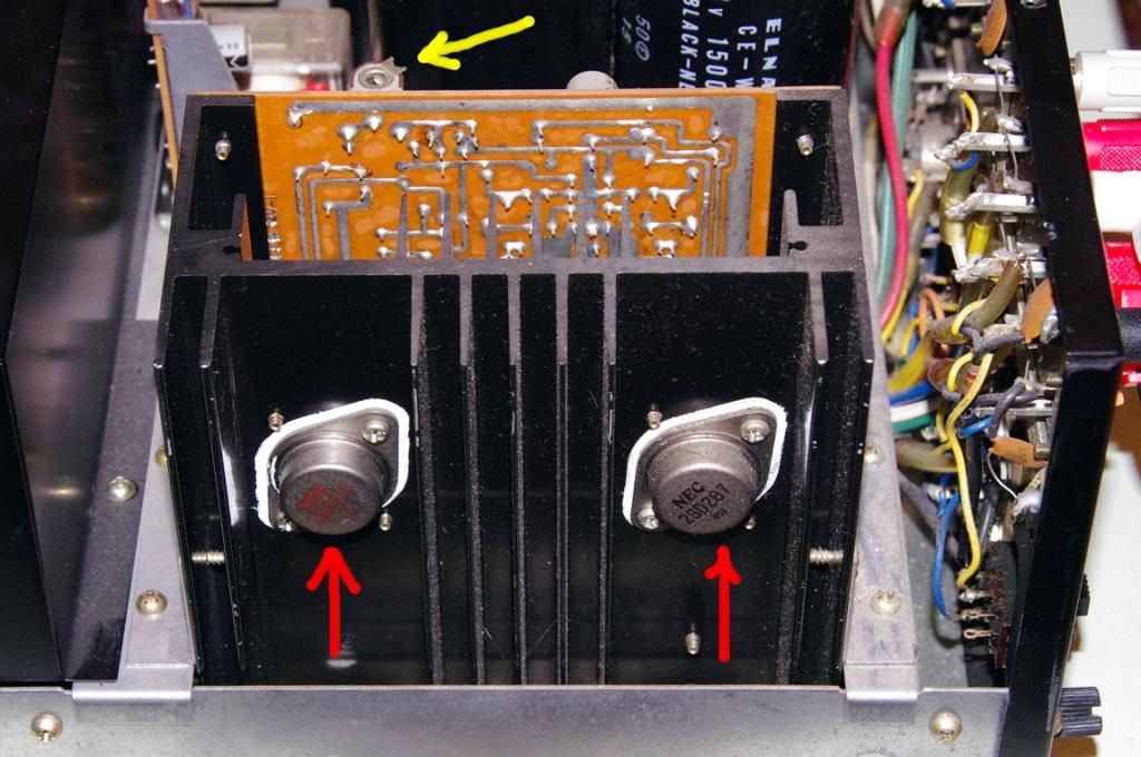
(Yellow arrow points to one of those bias trimmer pots.)
Based on the photo (the mica/thermal paste insulation behind the transistors), does it look like it needs to be changed. I think these are called TO-3 mica plate insulators? yes/no? If so this looks straight forward to do. I assume the E and C pins on the transistors are not soldered in place to the little boards on the other side of the heat sinks?
Next I was going to swap out the Electrolytic caps on the power supply board. Check bias, Test again.
After that, the electrolytic caps on the main amp boards. Once gaining access to those boards should I address some transistors on the main amp boards - specifically the 'matched' input pair?
I realize that the DC offset readings I have aren't terrible, but not great either. There is no trimmers to adjust DC offset. From what I have read, higher than 'desired' offset is caused by mis-matched input transistors?
Again, from what I have read, high DC offset causes distortion, and what I'm hearing is not distortion, so should I forget about these transistors for now? (I hope so, because NPN vs PNP, E,C,B pin out locations, "matched pair", etc is giving me a head ache.)
The other transistor I have read about located on the main amp boards is an 2SC1451, which is reported to be a problem child on this amp and other amps, yes/no?
Thanks again for the advice so far.
Just a few notes on what I had already done prior to the original posted question.
1. Service manual downloaded. Alternate (easier) method to adjust bias found. (DMM connected to main board pins 8 and 5; adjust to 30mV DC)
2. All pots and switches were cleaned after removing top/bottom covers, getting spray nozzle into the indentations, spraying, rotating, etc.
Results are all potentiometer controls work smoothly. No scratchiness, snaps, crackles or pops. No drop outs, just smooth transition across the range of volume and tone controls.
The problem was a weak right channel, and a generally weak, uninspiring audio quality.
From the first few replies I decided to try adjusting the bias - although I knew what to do, I was going to replace those original single turn trimmer pots with something like 25 turn pots before trying it. I got brave and gave it a shot with the originals. It went very smooth, although I don't have both boards dead on the recommended 30mV I did get them close, 29.7 to 29.9mV.
The result of that was that both channels now have equally balanced volume. So the weak right channel problem is resolved.
I might be wrong, but I think the main protection relay on the power supply board is OK. Very consistently clicks on a few seconds after power on. Then there is no funny behavior like one channel or the other dropping out.
But the audio quality still isn't awe inspiring when connected to my Pioneer CS-99 speakers. I normally run those from a Pioneer SX-1000TW that just sounds better to my ears.
I believe, however that this Kenwood KA-8006 will outshine the SX-1000TW with more attention.
Based on my limited knowledge, I planned to stay with the original capacitor specs, not upping the capacitance, and maybe not even the voltage unless I can't find an exact replacement.
And I was going to take this on in small chunks, testing after each phase.
My plan is to first swap out the 2 big filter caps; 15000uF 63V with the same value caps. Yes they are physically smaller, and I already have some 2" diameter PVC that I plan to use to hold the new smaller diameter caps. The original Elna caps are just about 2" diameter, new Rubycon's are about 1 3/8". Changing these 2 does not require much of any disassembly (like what will be required to get at the power supply board and the main amp boards.)
Regarding the comment to check the insulation at the output devices; is this what you are referring to (red arrows---> NEC Transistors) in the following photo?:
(Yellow arrow points to one of those bias trimmer pots.)
Based on the photo (the mica/thermal paste insulation behind the transistors), does it look like it needs to be changed. I think these are called TO-3 mica plate insulators? yes/no? If so this looks straight forward to do. I assume the E and C pins on the transistors are not soldered in place to the little boards on the other side of the heat sinks?
Next I was going to swap out the Electrolytic caps on the power supply board. Check bias, Test again.
After that, the electrolytic caps on the main amp boards. Once gaining access to those boards should I address some transistors on the main amp boards - specifically the 'matched' input pair?
I realize that the DC offset readings I have aren't terrible, but not great either. There is no trimmers to adjust DC offset. From what I have read, higher than 'desired' offset is caused by mis-matched input transistors?
Again, from what I have read, high DC offset causes distortion, and what I'm hearing is not distortion, so should I forget about these transistors for now? (I hope so, because NPN vs PNP, E,C,B pin out locations, "matched pair", etc is giving me a head ache.)
The other transistor I have read about located on the main amp boards is an 2SC1451, which is reported to be a problem child on this amp and other amps, yes/no?
Thanks again for the advice so far.
- Status
- Not open for further replies.