Hi,
I'm currently (hopefully) putting the finishing touches to a Kenwood L-01a refurb but have run into a potential problem.
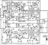
When setting this amps dc offset as per manual the offset on the preamp both channels don't settle on a value it does adjust but rapidly changes 10-20mv either way. Looking at the schematic is there anything that jumps out at anyone?
Thanks
I'm currently (hopefully) putting the finishing touches to a Kenwood L-01a refurb but have run into a potential problem.
When setting this amps dc offset as per manual the offset on the preamp both channels don't settle on a value it does adjust but rapidly changes 10-20mv either way. Looking at the schematic is there anything that jumps out at anyone?
Thanks
Attachments

You did have the volume turned down, didn't you? The trimpots are clean and operating smoothly as well?
Otherwise this suggests high levels of low-frequency noise. This amplifier appears to be all DC-coupled, so would merrily be amplifying any and all input FET 1/f noise. The only question is whether or not it is at normal levels for the µPA68H used. Both channels behaving exactly the same suggests that this may actually be the case.
BTW, the part of the schematic you're showing covers the (MM) phono preamp and power supply, but not the interesting part. 😉 Try this.
What I noticed is that input stage supply voltages are generated by zeners with capacitors in parallel. These caps (a) are not too generously sized to begin with (C15/16 should also be 35 V types really, they're 25 V parts in parallel to a 24 V zener) and (b) would not be effective near DC anyway. This could be another source of low-frequency noise. Finding some matching low-noise zeners to replace WZ-240, WZ-197 and XZ-051 may be worth a shot.
Attachments

I'd start resoldering the whole PCB first.Hopefully you didn't changed the capacitors with much bigger ones in volume...especially c17. There's a reason for using lower rating capacitors...they might be leaky, but they aren't big antennas either...
Last edited:
If both sides are doing it, it would have to be something central, like maybe the ground connection. Looking at that certainly can't hurt.
I get worried about cap "upgrades" when people start replacing small electrolytics with big honkin' overrated film caps originally intended for speaker crossovers. With past advances in manufacturing, a 33µ/25V of 40 years ago may be as big as a decent 47-68µ/35V today already.
I get worried about cap "upgrades" when people start replacing small electrolytics with big honkin' overrated film caps originally intended for speaker crossovers. With past advances in manufacturing, a 33µ/25V of 40 years ago may be as big as a decent 47-68µ/35V today already.
You did have the volume turned down, didn't you? The trimpots are clean and operating smoothly as well?
Yes volume control turned down all other controls flat and the trimpots are new Bourns sealed multiturn types
BTW, the part of the schematic you're showing covers the (MM) phono preamp and power supply, but not the interesting part.
There are two adjustments for dc offset the ones you referenced here are rock solid, the problem one is highlighted in the attached image (trimpots and adjust points).
I'd start resoldering the whole PCB first. Hopefully you didn't changed the capacitors with much bigger ones in volume...especially c17. There's a reason for using lower rating capacitors...they might be leaky, but they aren't big antennas either...
The boards have been resoldered and it has been recapped to original values
If both sides are doing it, it would have to be something central, like maybe the ground connection. Looking at that certainly can't hurt.
I'll check these and add some serrated washers if I feel necessary.
Attachments

I hope you have checked that none carry more than ~1 mA or so? Multiturn pots generally are not really designed for carrying much current at all.Yes volume control turned down all other controls flat and the trimpots are new Bourns sealed multiturn types
Oh, so it is the phonopre after all.There are two adjustments for dc offset the ones you referenced here are rock solid, the problem one is highlighted in the attached image (trimpots and adjust points).
Phonopres have an absolute ton of low-frequency gain. It's 20 dB higher than nominal at 1 kHz, and that seems to be 38 dB, so we're talking like 58 dB or 800 - right down to DC at the given test points. Normally you'd be seeing either a capacitor in the feedback network's ground leg or a DC servo, both with the same goal: bringing down gain near DC to unity and eliminating manual offset adjustments. Not so here. This circuit must be adjusted manually and is relying purely on its no doubt good linearity for keeping intermodulation from strong low-frequency components at bay (of which among uneven records and tonearm resonance, vinyl playback has plenty to offer). Low-frequency rolloff is then provided via the 4.7 µF / 35 V bipolar / 15 kOhm highpass that follows, with optional further AC coupling and an optional subsonic filter following later on.
In sum, I think what you are seeing is normal and expected. The adjustment could be off by +/- 1 V and I still wouldn't see it as particularly critical - there is plenty of voltage headroom. You've got it dialed in perfectly fine.
For vinyl playback, I'd be leaving DC OFF and Subsonic ON.
Last edited:
Is it possible to get a schematic with better resolution?
It's hard to see the parts values.
I would like to sim this MM preamp in LTSpice.
It's hard to see the parts values.
I would like to sim this MM preamp in LTSpice.
Is it possible to get a schematic with better resolution?
It's hard to see the parts values.
I would like to sim this MM preamp in LTSpice.
It's hard to see the parts values.
I would like to sim this MM preamp in LTSpice.
Edit: just found the service manual.
I'm already cloning a Luxman C50 phono preamp, so I thought this one might be an option to look at.
I'll see if I can sim it.
I'm already cloning a Luxman C50 phono preamp, so I thought this one might be an option to look at.
I'll see if I can sim it.
- Home
- Amplifiers
- Solid State
- Kenwood l-01a dc offset