First, I am new to repairs. I have Perry's repair tutorial that I am working my way through, but because of all the info that it has, it is somewhat overwhelming.
On to the problem/question: 🙁
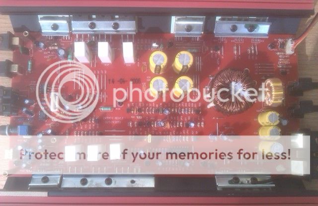
I have a Kicker ZX300.1 monoblock that flashes Green to Red.
The circuit board has a date of 14-04-2006 and is a Rev 1.2
I have remove the output transistors from the board and checked them and they appear fine to me. They read as the tutorial says that they should. There are (3) C5242A and (3) C1962A. They are connected to a large ceramic resistor each, which has 5W0.2ohmJ printed on the sides. I measeured them with the transistors out of the board and they appear to be within tolerance. 😕
Here are the voltages on the TL494 IC
1) fluctuates from 1.07 - 1.22
2) 3.3 🙂
3) 0 and then up to 5 when the red protect light flashes 😱
4) 0
5) 1.5
6) 3.42 🙂
7) 0 🙂
8) & 11) 4.5 then fades to 0 when the red protect light flashes 😱
9) & 10) 1.67 then fades to 0 when the red protect light flashes 😱
12) 12 🙂
13) - 15) 5 🙂
16) 3 then climbs to 9 when the red protect light flashes

Nothing appears to be burnt on the board
I do not have a scope and know that I need to invest in a better meter. With that being said,
Any help and direction is greatly appreciated.
Thanks,
😎
On to the problem/question: 🙁
I have a Kicker ZX300.1 monoblock that flashes Green to Red.
The circuit board has a date of 14-04-2006 and is a Rev 1.2
I have remove the output transistors from the board and checked them and they appear fine to me. They read as the tutorial says that they should. There are (3) C5242A and (3) C1962A. They are connected to a large ceramic resistor each, which has 5W0.2ohmJ printed on the sides. I measeured them with the transistors out of the board and they appear to be within tolerance. 😕
Here are the voltages on the TL494 IC
1) fluctuates from 1.07 - 1.22
2) 3.3 🙂
3) 0 and then up to 5 when the red protect light flashes 😱
4) 0
5) 1.5
6) 3.42 🙂
7) 0 🙂
8) & 11) 4.5 then fades to 0 when the red protect light flashes 😱
9) & 10) 1.67 then fades to 0 when the red protect light flashes 😱
12) 12 🙂
13) - 15) 5 🙂
16) 3 then climbs to 9 when the red protect light flashes
Nothing appears to be burnt on the board
I do not have a scope and know that I need to invest in a better meter. With that being said,
Any help and direction is greatly appreciated.
Thanks,
😎
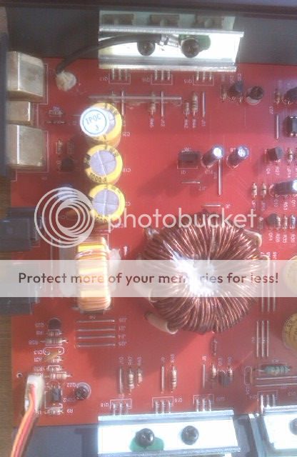
As much as I know that you do not like them, these were taken with a cell phone. It is the only thing I have at my disposal until much later.
Thanks,
There is also a small circuit board that is not pictured that sits elevated on the end with the RCA's. I think it is the crossover section because it has the swithech for that on it (and the bass know input).
Thanks,
There is also a small circuit board that is not pictured that sits elevated on the end with the RCA's. I think it is the crossover section because it has the swithech for that on it (and the bass know input).
No,
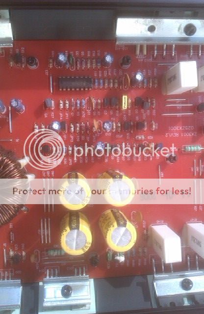
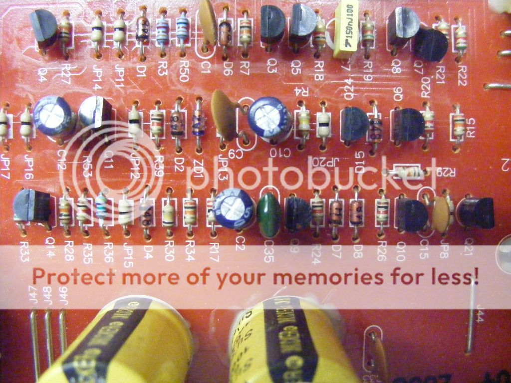
In the third picture from the top, pin 16 is in the lower right corner. Just below it is a capacitor. To the right of the capacitor is a Zener Diode and to the left are two light blue resistors. These are all connected to pin 16 by a trace on the bottom of the board.
Here are the component markings and board designations
Zener - 48 - D6
Cap - 104 100V - C1
Res - brown, black, red, gold, brown - which I interpret 1000 5% 1% - R50
Res - brown, red, brown, gold, brown 120 5% 1% - R3
I may be interpreting the values wrong.
Desolder 1 leg of the diode (not likely a zener and likely marked 1N4148). Does that allow the amp to power up?
I strongly recommend clamping all semiconductors tightly to the heatsink and inserting a 10-15 amp fuse or a current limiter inline.
I strongly recommend clamping all semiconductors tightly to the heatsink and inserting a 10-15 amp fuse or a current limiter inline.
With 1 leg of the diode desoldered & removed, the amp powers up and does not flash the red protect light, it just stays Green. 🙂
Does that diode connect to a transistor in the audio section of the amp? There may be a resistor in series between the diode and transistor.
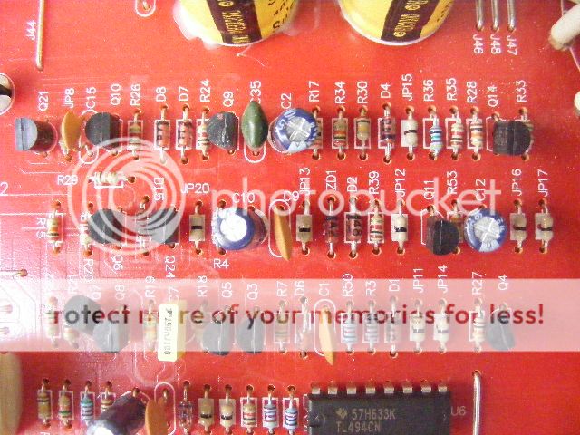
The trace connects to two capacitors and a resistor and it ends at an emitter (left leg) of a 2N 4401 (Q6). This transistor is located in the middle of 3 rows below the IC, last on the right (third picture from the top).
The capacitors and resistor jumps to another trace that connects to another emitter of a 2N 4401 (Q9). Two more capacitors and a jumper are also connected to this trace. This transistor (and the two capacitors) are in the bottom of the three rows and is located just above the top right yellow capacitor.
The capacitors and resistor jumps to another trace that connects to another emitter of a 2N 4401 (Q9). Two more capacitors and a jumper are also connected to this trace. This transistor (and the two capacitors) are in the bottom of the three rows and is located just above the top right yellow capacitor.
Reinstall the diode and remove Q6 and Q9, one at a time. Which one, when removed, allows the amp to power up?
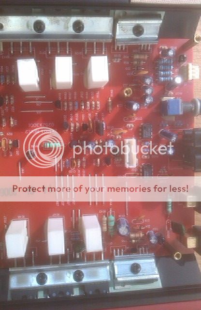
Can you post better photos for this area of the board so that the circuit board designations are legible?
Can you post better photos for this area of the board so that the circuit board designations are legible?
Perry, I hope that these are to your liking.
Q6 removed - powers up without going into protect
Q6 replaced & Q9 removed - goes into protect mode.
I have more pictures of this board at this quality if you would like them. I can email them to you or you can download them off of my photobucket account. I have not uploaded them all yet though.
Q6 removed - powers up without going into protect
Q6 replaced & Q9 removed - goes into protect mode.
I have more pictures of this board at this quality if you would like them. I can email them to you or you can download them off of my photobucket account. I have not uploaded them all yet though.
What does the base (center leg) of Q6 go to? If it goes to a resistor, follow the circuit beyond the resistor.
Those photos are much better. I'll ask for them as needed.
Those photos are much better. I'll ask for them as needed.
Q5 checks out OK, I could not find any leakage between any combination of legs.
The base of Q5 goes through R15 and into J36. The other end of J36 connects to the collector of Q115
Here is a picture of Q115
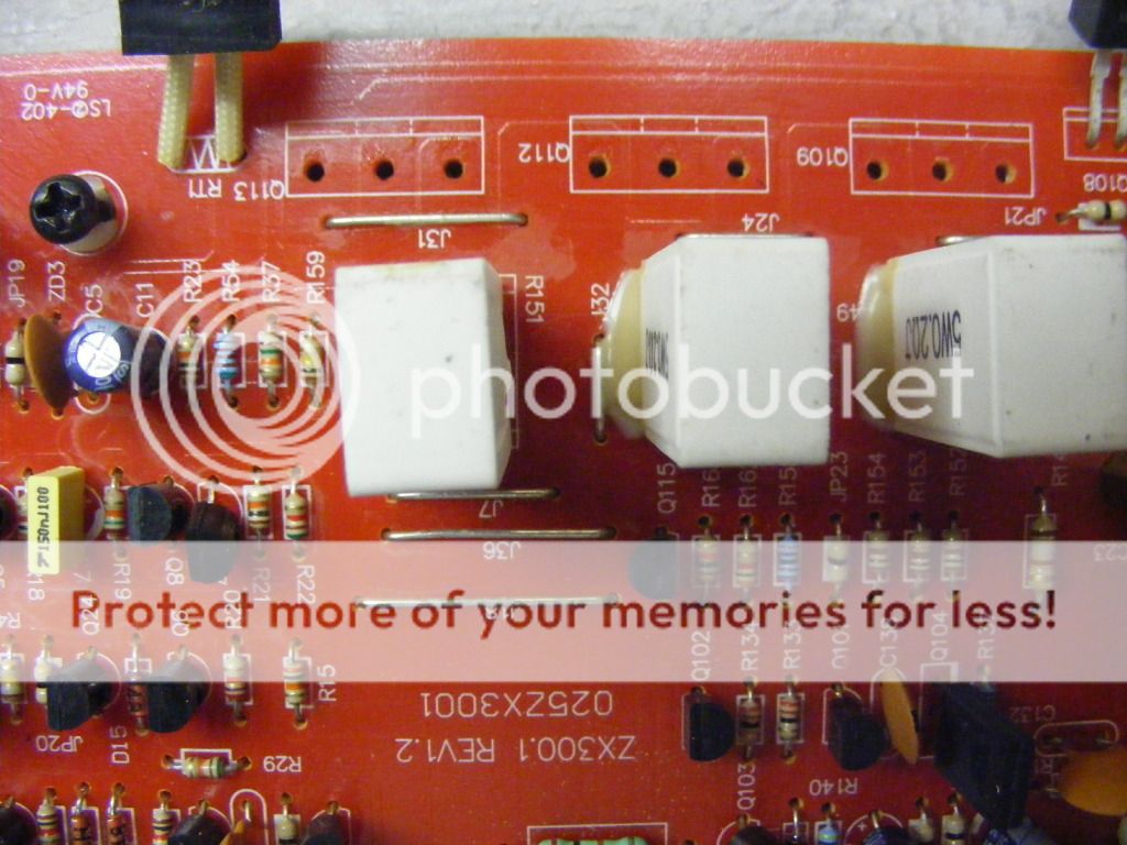
The base of Q5 goes through R15 and into J36. The other end of J36 connects to the collector of Q115
Here is a picture of Q115
With Q6 in the circuit and either of the two transistors mentioned above out of the circuit, does it power up normally?
I followed your direction and kept going "down" the traces removing and testing transistors that were in line. I found a MPS A92 (Q114) that has a leak or short between the emitter and collector. I am in the process of obtaining a replacement. Once I have it back in I will test again to see if it will power up without going into protect mode.
Thanks for the help
Thanks for the help
OK, I finally was able to free up some time and put a new transistor in. The amp powered up without going into protect mode and has output. So I put it all back together for more testing.
I currently have it hooked to be put under strain (installed in my car). So far all is well. 😀
Thanks for the help Perry, you are a blessing. 🙂
😎
I currently have it hooked to be put under strain (installed in my car). So far all is well. 😀
Thanks for the help Perry, you are a blessing. 🙂
😎
- Status
- Not open for further replies.
- Home
- General Interest
- Car Audio
- Kicker ZX300.1 going into Protect mode, I need help