I have a 2008 Kicker ZX650.4 that originally was installed on a wakeboard board. It was in constant protect. Found some water ingress on one channel of the power supply FET's. I had to replace the large input capacitors (swollen vents and measured at 10% capacity) and the power supply FET's. I have looked all over the board (top and bottom) for other obvious issues but do not see anything. When I use a tablet as a source, I get audio output, but it seems lower than I would expect. With the gain maxed, it is audible, but much lower than I would expect. I looked through a couple of PapaZBill's posts on similar amps and I've come to the conclusion I need some help identifying some specifics on this amp. The muting circuit seems like a common issue on these amps, but I'm having a hard time figuring out which components are relevant here. Also not sure if have any output means the muting circuit is fine or if it would completely mute it on these amps.
I have rail voltage at the power supplies and at all 4 sets of output transistors (~+/-35V if I remember off hand). The +/- 15V regulators also seem OK. Amp draws about 1.5 amps at idle. I'm not sure what the exact voltages on the exact pins should be at the daughterboard, but I have a mix of the +/-15V, battery voltage, and remote voltage. No components seem overly hot. The gain knob seems to affect the volume, as do the crossover knobs and switches.
Any help would be appreciated.
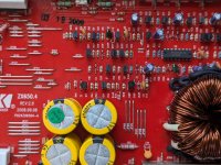
Attachments


When I get back to my bench I'll check, but according to this post https://www.diyaudio.com/community/threads/kicker-kx650-4-audio-problems.331344/post-5638020 (which are similar ref des and component values to mine) they are not similar to what you posted. Now saying that I can't say right now that the basic design is not correct. There are apparently enough differences between the KX and ZX that I just wanted to make sure I knew what I was looking at.
I'll check it and report back.
I'll check it and report back.
I could not determine that this board is the same as what you sent. I looked through all the 2N4403's in the zoomed out picture and could never find anything directly tied to remote (looking for the Q4 equivalent in your linked schematic page). I put my remote at 9V and my supply at 13.5V to be able to tell the difference, but could not find 9V there. The amp still turned on fine with 9V remote. The reference designators are certainly different also. As noted in the older thread, I did find some of those components, but their values appear different than in that post. So trying to determine if my measured values are good or bad seemed like a rabbit hole without some more information.
Attachments

At this point, is the only problem that the audio level is low?
Did you try removing the muting transistors to see if the audio returned to expected levels?
Did you try removing the muting transistors to see if the audio returned to expected levels?
Yes, the only problem I have is the audio level is low. I have not removed the muting transistors at the the input to the output section yet. Since all 4 channels behave the same, I assumed it would be the "control" of the muting circuit that would be the issue.
Would it be fine to just remove one of them and see if just that channel comes back? I assume with the muting transistor out on that one channel it would still be fine even if the other 3 were being muted.
Would it be fine to just remove one of them and see if just that channel comes back? I assume with the muting transistor out on that one channel it would still be fine even if the other 3 were being muted.
You have to start somewhere and the muting transistors are the easiest. Yes. one is generally enough but I'd try two if one doesn't show a difference.
There are four J110 FETs on the input to each channel. Q100,Q200,Q300 & Q400 all DC coupled to the mute control circuit, which should apply a ~(-20) volts to the gates of each FET pinching off the source/drain channel, allowing signal to pass w/o being shunted to ground.
The muting control circuit consists of D10P-1N4148, ZD3P-15v zener tied to the gate of Q18P-BS170. Q14-2N4403 between Q18P and Q15-2N4401 and Z3-1N5250B(20v) zener, anode tied to the emitter of Q15. -VCC tied to Z3 anode. Soft Start voltage tied to Q18P drain and Q14 emitter. The muting line comes off the collector of Q15.
The mute control circuit was usually where the problem lies. I don't recall what typically fails. If you will check DC voltages around all transistors and diodes, including Q6-2N4403 and post as so:
anode cathode
Z3
ZD3P
D10P
emitter base collector
Q14
Q15
Q6
drain gate source
Q18P
I will search my notes in the meantime It's been a minute!!
Thanks for the detailed info. Mine is certainly still muted. I get ground at all of the muting transistors (Q100,200,300,400) and also at the collector of Q15. Below are all my voltages (referenced to ground.... speaker and power ground look to be tied together with a 0 ohm resistor on this amp). All measurements in Volts.
| anode | cathode | |
| Z3 | -20.26 | .002 |
| ZD3P | .002 | .07 |
| D10P | .113 | .07 |
| emitter | base | collector | |
| Q14 | .22 | .002 | -19.34 |
| Q15 | -20.36 | -20.26 | .002 |
| Q6 | 13.36 | 12.54 | 13.27 |
| drain | gate | source | |
| Q18 | .233 | .115 | .002 |
Last edited:
You should have a ~(-20v) at the collector of Q15. This leaves the Q100,200,300,400 J110 FET's muted.
Because you have 13.36v(Soft Start) from the emitter of Q6,, you should have 8.15v at the Drain of Q18P, instead its .233v. There are several culprits including an open resistor R44P-30K ohm, failed Q18P or Q14. There might be a broken trace, Be sure that Q14,Q18P, ZD3P,Z3,R34,and R46 are connected to signal ground.
Because you have 13.36v(Soft Start) from the emitter of Q6,, you should have 8.15v at the Drain of Q18P, instead its .233v. There are several culprits including an open resistor R44P-30K ohm, failed Q18P or Q14. There might be a broken trace, Be sure that Q14,Q18P, ZD3P,Z3,R34,and R46 are connected to signal ground.
R44P appears to be the culprit. Measures 300k in circuit. As a quick check, I had a 33k leaded resistor laying around. I just placed it across it for a test, and the amp now plays at full volume. I'll get it properly replaced with a 30k and report back. The original resistor looks fine with no obvious marks, but it obviously is not. Should I potentially see if I can find a higher rated power resistor?

- Home
- General Interest
- Car Audio
- Kicker ZX650.4 Low Output