I been trying to calculate Butterworth 3rd order PLLXO LC.
The approach I am using is standard filter tables to lookup L and C values.
Typically for these are: 1 2 1.
Then denomalize for frequency and input/output resistance.
I can verify that my calculations are correct using various filter calculators and other examples.
Things get funky when I compare results with crossover calculators, they seem to be using different normalized values as a starting point: 0.5 1.333 1.5555 in this case.
What am I missing here? is there something special about crossovers that I am not considering, I suspect it something to do with dissipation factor?
Thanks,
Rafal
Heh,I remember M&K used to ship a line-level, passive crossover. Had 2 toroids about 4" in diameter, about 2" tall and crappy caps. 🙂
Best,
E
Best,
E
I must be one of the few people on the internet who have great enthusiasm for BW3. 😱
There is a wildly sensible enthusiasm for 12dB/octave LR2. And people like 24dB/octave LR4. But the Cinderella candidate is 18dB/octave BW3. It's as valid as the other two from a mathematical point of view.
Thing is that the even-ordered filters get frequency response quite flat. What they don't do is get power response flat. Or impedance. And flat impedance is something power amplifiers like too.
Some combinations work better with BW3 than others. If you do it with a 5" or 6" bass, there might be something to be said for recessing the driver. BW3 relies on a 3:1 ratio of filter components. Just how it works. A fantastic hexagonal symmetry at the root of it. Sort of thing that appeals to my inner mathematician. 😎
Attachments


Depending on the frequency looking at range of 0.5 to 2.5H, these are availible from Cinemag and others but I want to make sure I get my calculations right before spending the money.PLLXO with L & C is going to require huge L values… i have yet to find a suitable source.
dave
Why not take a standard opamp circuit?
Trying to keep silicon out of signal path as it is all tube system. I am using miniDSP with JMLC alignment and are happy with the results so would like to try it with passive crossover.
What software and calculators are you using? Some Spice type or dedicated filter software?
FWIW, I often end up at 3rd order electrical, too. Just seems to be what works.
FWIW, I often end up at 3rd order electrical, too. Just seems to be what works.
just to be pedantic - trying to keep silicon out of the signal path while using miniDSP?
Steve - as valid as your observations may be, I think the OP is asking about line level passives, and they do tend to get complicated with the higher order topologies.
Steve - as valid as your observations may be, I think the OP is asking about line level passives, and they do tend to get complicated with the higher order topologies.
🙄Trying to keep silicon out of signal path . . . . I am using miniDSP . . . .
You beat me, Chris.
I think he wants to take the miniDSP out and replace with an LC passive line level XO. Should be fairly straight forward if one can get the large chokes needed.
Given a highly restistive input in the form of power amps, text book formulas should be you 3rd order electrical BW.
dave
Given a highly restistive input in the form of power amps, text book formulas should be you 3rd order electrical BW.
dave
I just ran the idea of passive filters into, say, a 2K input impedance of an inverted op-amp. It's ludicrous values for chokes! 😱
2-Way Crossover Calculator / Designer
160mH is going to be about the size of a car-battery. And dubious on linearity. Never mind that it will probably act like a radio antenna. You'll be picking up the BBC's Radio 2!
I used to build op-amp audio filters about 40 years ago, so excuse me if I am a bit rusty. I used to use TLO74 or NE5532 devices with a few smallish capacitors and the usual resistors. No coils at all needed.
Butterworth filter - Wikipedia
I think it's OK to use line-level bafflestep correction which is just an RC filter:
Arpeggio Loudspeaker - diyAudio
But this line-level approach really doesn't work here.
Attachments


Last edited:
just to be pedantic - trying to keep silicon out of the signal path while using miniDSP?
MiniDSP to measure and evaluate different crossover arrangements only.
I just ran the idea of passive filters into, say, a 2K input impedance of an inverted op-amp. It's ludicrous values for chokes! 😱
...160mH is going to be about the size of a car-battery.
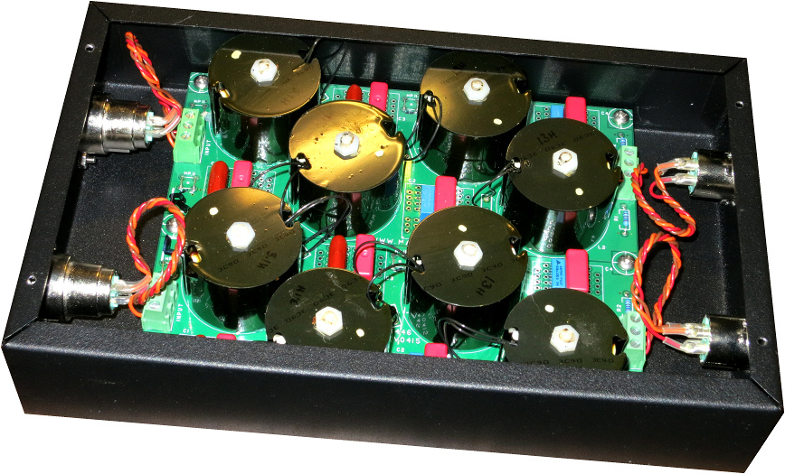
10k minimum is more realistic, but even the Marchand ones use a 5k termination on the board (meaning you need a really low Z output on the pre. Because they need to handle very low current, they can use very skinny wire and be cored. A look at the Marchand chokes will give an idea of what is possible (XLRs on the box will give a sense of scale). It might actually be cheaper to buy this than to get a set of 1-off chokes.
I used to build op-amp audio filters about 40 years ago, so excuse me if I am a bit rusty. I used to use TLO74 or NE5532 devices with a few smallish capacitors and the usual resistors. No coils at all needed.
An OpAmp uses feedback. An RC only PLLXO is possible but with no FB 2nd order is kinda droopy, and really needs a HF amp with high input Z (>50k or so). 1st order is very doable. We use it often.
dave
Perhaps the GIC blocks of my Synergy "active" crossover sandwiched between a couple of valve buffers would do the trick... It still has opamps, but they are in shunt configuration (simulated coils)...
Bit of an evolution of SY's acheron, replacing the S&K of the bass circuit with an FDNR. What I did uses jfets for the buffers (basically DC B1's).
Rick was going to build one and compare to the LC PLLXO but not sure whether he did it as he was so happy with his PLLXO... http://www.diyaudio.com/forums/analog-line-level/164886-synergy-active-crossover-8.html#post4995206
Tony.
Last edited:
And flat impedance is something power amplifiers like too.
Good amplifiers don't care 😛
if its a tube amp system and one can stand the thoughts of active filters, then maybe Steve Bench's schematic would be a good compromise
http://www.jacmusic.com/techcorner/SBENCH-PAGES/sbench101/Crossover/xover.gif
http://www.jacmusic.com/techcorner/SBENCH-PAGES/sbench101/Crossover/xover.gif
Good amplifiers don't care 😛
Low output impedance amps don’t care… that spec does not make them good or bad.
dave
I pulled a pair of 10VA transformers from the charging circuit of an uninterruptible 2x40W fluoro, 80H primaries. Self resonance was at 800Hz though (and so was my crossover, so..) but you get my point.It's ludicrous values for chokes! 😱
Impedance is everything. Valve circuits are good 😉. Useful iron can be found. The only iron I use that is the size of a car battery is in my bass amp supply filter, and that passes 5A.
I like to shield line level coils.it will probably act like a radio antenna.
Perhaps there are two questions.
And if it has to stay passive, why not speaker level? At least the parts would be easier to find.
You may have very good reasons why, but we don't know what they are.
- Why passive?
- Why line level?
And if it has to stay passive, why not speaker level? At least the parts would be easier to find.
You may have very good reasons why, but we don't know what they are.
- Home
- Loudspeakers
- Multi-Way
- Line level crossover calculations help