After my last experience with relatively high power SET amplifier (see https://www.diyaudio.com/forums/tubes-valves/327637-lian-845-set-kit-commercial-product.html ), I started thinking about upping the game and getting into power range comparable with push-pull tube amplifiers. There are two ways get there — either use high power tube like 833 or using tube in A2 class where grid gets positive in relation with cathode.
Tubes like 833 require even higher voltages than 845 or 211 and very high output impedance requires extraordinary effort to make output transformer compatible with it and still have enough bandwidth for full range audio. That will result in very expensive design, with a lot of full custom components. Example of that approach is WAVAC 833. But for the $350K price results ( Wavac SH-833 monoblock power amplifier Measurements | Stereophile.com ) are not very impressive.
A2 class though can allow lower plate voltages with higher current, thus reducing requirements to power supply and transformer design. Load impedance 4-6K ohms is very much achievable without extraordinary effort. With output tube operating with grid current you need to have low impedance driver circuit. Easiest way to achieve that is using cathode follower with direct connection to grid of output tube. It is possible to use 845 or 211 tube that way, but there are also other tubes which were design to have grid current almost at all signal levels. One of examples is 805/838 tube. The only real difference between them is that original 805 had a plate cup, and 838 did not. Today China makes 838 equivalent, which for some reason they call 805. Thus when you buy a new production 805 tube, you are getting 838. Of cause neither of these tubes is really affordable as NOS — they almost all gone and were not manufactured outside of China for decades.
I didn’t want to do build from scratch and just like with 845 based amplifier I referenced above, I decided to get a modern Chinese amplifier and start from there. Line Magnetics is a mid-range Chinese brand which builds and markets tube amplifiers all over the world. They have amplifier based on 805 tube which is claimed to reach 48W of output power. Price (if you buy direct from China) is in relatively affordable range, even when one account for international shipping charges. And finally I made a move and placed on line order.
After 3 weeks of waiting UPS guy knock on my door, and when I opened it, large cartoon box was sitting next to it. The box has some signs of tear, which is explainable (it“s path was from mainland China to Honk Kong, to Japan, to Chicago and finally to Dallas). But when I opened it — everything inside was in pristine shape. Tripple boxing and attention to packing details did the job.
One note — when you buy direct from China, you likely getting the version that requires 220 volts power line. Some devices can be modified to use 120V, some are not. From what I read about Line Magnetics gear, I thought that I will be able to easily convert it with s bit of soldering around power transformer. But I also had a boost transformer, which I purchased many years ago, but never put in service. Thus I was ready to use amplifier out of the box too. As alternative, you can arrange 240V outlet in you music room — many audiophiles have it already. If you do not, getting step up transformer is much cheaper than hiring electrician. In the end I found that my version of amplifier (made some time in late 2019) does not allows easy voltage change, and I kept it running with boost transformer. But to use in my high-endish music room I bout another transformer, which simply looks more in place (UMI Step UP 110 to 220 Voltage Converter found on Amazon). It is rated for 1200VA which is well enough for amplifier that consumes 500W.
Line Magnetic LM-508ia has excellent fit and finish. Designers had clear attention to details and manufacturing quality was excellent. All chassis is covered with mirror like enamel probably ½ mm thick. Connectors for inputs and speaker outputs are of high quality. Amplifier came with pair of Line Magnetic branded Chinese 805 tubes, pair of also LM branded 300B tubes (used as drivers), pair of new production Electro-Harmonic 6SN7made in Russia, and a Chinese 6N9P (equivalent of 6SL7) tube of unknown brand. Later we will see that this amplifier works best with tubes that came with it from the factory.
LM-508ia has two adjustments — output tube current and hum balancing. When I turned it on, both of these adjustments were spot on. It only can be explained if each unit is tested and adjusted right before it is packed into the box.
This amplifier has simple classic circuit (see Pic.1) : there are two stages of amplification which are classic resistor amplifiers with half of 6SL7 and paralleled 6SN7, loaded with 300B as cathode follower directly connected to grid of 805 tube. The latter has relatively low plate voltage, and grid is positive at idle. 300B operates with negative cathode source and idle current at about 40mA, while output tube is biased to 120mA of plate current. All that results in constant power consumption of about 500W. Power consumption does not change while you play music — this amplifier really operates in A class. Al power sources use solid state rectification and CLC filtering. Circuit includes timer that delays high voltage until all tubes are warmed up. Additional digital circuit is used for remotely controlled volume pot. I used this unit as pure power amplifier and thus remote control was put back in the box until I decide to sell it.
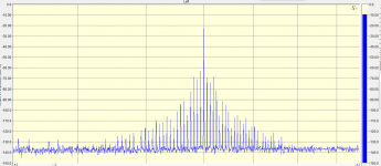
LM-508ia has three regular inputs, which can be selected with front switch and affected by volume control, and fourth input that bypasses volume pot and designed for use with per-amplifier. Unfortunately the circuit does not change and all gain stages are used in either case. Thus the only advantage of using fourth input — it ignores volume control setting. But noise/him level stays the same regardless of which input you use. Like almost all tube amplifier, this unit has some hiss and noise at the output which can be heard through speakers when you are close to them (my reference solid state Bryston is dead quiet in comparison), but I didn’t hear any hum from my sitting position 8 feet away. I measured AC noise at speaker and it was below 2mV. Main type of noise is random hiss and some hum like sound from 60Hz power line frequency and its harmonics. Pic.2 shows spectrum of noise as it was measured by me.
Before putting amplifier on my workbench, I decided to play few records with it. The result was generally positive. It plays loud enough through my 89db/W speakers without obvious signs of clipping. Overall sound was something between my 845 based amplifier (it was not as soft) and solid state Bryston (LM still played like tube amplifier). There is one more setting switch available — it adjust amount of global negative feedback to listener“s liking. Unlike A1 class amplifiers, this amplifier needs some amount of negative feedback to reduce distortion and output impedance to make it compatible with modern speakers using complex crossovers. I initially use 8 ohm output and least amount of feedback (almost none), but bass was uncontrollable. Increasing feedback to second position improved sound significantly. I also tried to use 4 ohm outputs and like it more. In the end the best for my speakers was 4 ohm output and second setting of feedback. When I tried to increase feedback, bass became even tighter, but overall sound stage started collapse. It is clear why variable feedback feature was included — make amplifier work best with various speakers.
>>>see follow up below<<<
Tubes like 833 require even higher voltages than 845 or 211 and very high output impedance requires extraordinary effort to make output transformer compatible with it and still have enough bandwidth for full range audio. That will result in very expensive design, with a lot of full custom components. Example of that approach is WAVAC 833. But for the $350K price results ( Wavac SH-833 monoblock power amplifier Measurements | Stereophile.com ) are not very impressive.
A2 class though can allow lower plate voltages with higher current, thus reducing requirements to power supply and transformer design. Load impedance 4-6K ohms is very much achievable without extraordinary effort. With output tube operating with grid current you need to have low impedance driver circuit. Easiest way to achieve that is using cathode follower with direct connection to grid of output tube. It is possible to use 845 or 211 tube that way, but there are also other tubes which were design to have grid current almost at all signal levels. One of examples is 805/838 tube. The only real difference between them is that original 805 had a plate cup, and 838 did not. Today China makes 838 equivalent, which for some reason they call 805. Thus when you buy a new production 805 tube, you are getting 838. Of cause neither of these tubes is really affordable as NOS — they almost all gone and were not manufactured outside of China for decades.
I didn’t want to do build from scratch and just like with 845 based amplifier I referenced above, I decided to get a modern Chinese amplifier and start from there. Line Magnetics is a mid-range Chinese brand which builds and markets tube amplifiers all over the world. They have amplifier based on 805 tube which is claimed to reach 48W of output power. Price (if you buy direct from China) is in relatively affordable range, even when one account for international shipping charges. And finally I made a move and placed on line order.
After 3 weeks of waiting UPS guy knock on my door, and when I opened it, large cartoon box was sitting next to it. The box has some signs of tear, which is explainable (it“s path was from mainland China to Honk Kong, to Japan, to Chicago and finally to Dallas). But when I opened it — everything inside was in pristine shape. Tripple boxing and attention to packing details did the job.
One note — when you buy direct from China, you likely getting the version that requires 220 volts power line. Some devices can be modified to use 120V, some are not. From what I read about Line Magnetics gear, I thought that I will be able to easily convert it with s bit of soldering around power transformer. But I also had a boost transformer, which I purchased many years ago, but never put in service. Thus I was ready to use amplifier out of the box too. As alternative, you can arrange 240V outlet in you music room — many audiophiles have it already. If you do not, getting step up transformer is much cheaper than hiring electrician. In the end I found that my version of amplifier (made some time in late 2019) does not allows easy voltage change, and I kept it running with boost transformer. But to use in my high-endish music room I bout another transformer, which simply looks more in place (UMI Step UP 110 to 220 Voltage Converter found on Amazon). It is rated for 1200VA which is well enough for amplifier that consumes 500W.
Line Magnetic LM-508ia has excellent fit and finish. Designers had clear attention to details and manufacturing quality was excellent. All chassis is covered with mirror like enamel probably ½ mm thick. Connectors for inputs and speaker outputs are of high quality. Amplifier came with pair of Line Magnetic branded Chinese 805 tubes, pair of also LM branded 300B tubes (used as drivers), pair of new production Electro-Harmonic 6SN7made in Russia, and a Chinese 6N9P (equivalent of 6SL7) tube of unknown brand. Later we will see that this amplifier works best with tubes that came with it from the factory.
LM-508ia has two adjustments — output tube current and hum balancing. When I turned it on, both of these adjustments were spot on. It only can be explained if each unit is tested and adjusted right before it is packed into the box.
This amplifier has simple classic circuit (see Pic.1) : there are two stages of amplification which are classic resistor amplifiers with half of 6SL7 and paralleled 6SN7, loaded with 300B as cathode follower directly connected to grid of 805 tube. The latter has relatively low plate voltage, and grid is positive at idle. 300B operates with negative cathode source and idle current at about 40mA, while output tube is biased to 120mA of plate current. All that results in constant power consumption of about 500W. Power consumption does not change while you play music — this amplifier really operates in A class. Al power sources use solid state rectification and CLC filtering. Circuit includes timer that delays high voltage until all tubes are warmed up. Additional digital circuit is used for remotely controlled volume pot. I used this unit as pure power amplifier and thus remote control was put back in the box until I decide to sell it.
LM-508ia has three regular inputs, which can be selected with front switch and affected by volume control, and fourth input that bypasses volume pot and designed for use with per-amplifier. Unfortunately the circuit does not change and all gain stages are used in either case. Thus the only advantage of using fourth input — it ignores volume control setting. But noise/him level stays the same regardless of which input you use. Like almost all tube amplifier, this unit has some hiss and noise at the output which can be heard through speakers when you are close to them (my reference solid state Bryston is dead quiet in comparison), but I didn’t hear any hum from my sitting position 8 feet away. I measured AC noise at speaker and it was below 2mV. Main type of noise is random hiss and some hum like sound from 60Hz power line frequency and its harmonics. Pic.2 shows spectrum of noise as it was measured by me.
Before putting amplifier on my workbench, I decided to play few records with it. The result was generally positive. It plays loud enough through my 89db/W speakers without obvious signs of clipping. Overall sound was something between my 845 based amplifier (it was not as soft) and solid state Bryston (LM still played like tube amplifier). There is one more setting switch available — it adjust amount of global negative feedback to listener“s liking. Unlike A1 class amplifiers, this amplifier needs some amount of negative feedback to reduce distortion and output impedance to make it compatible with modern speakers using complex crossovers. I initially use 8 ohm output and least amount of feedback (almost none), but bass was uncontrollable. Increasing feedback to second position improved sound significantly. I also tried to use 4 ohm outputs and like it more. In the end the best for my speakers was 4 ohm output and second setting of feedback. When I tried to increase feedback, bass became even tighter, but overall sound stage started collapse. It is clear why variable feedback feature was included — make amplifier work best with various speakers.
>>>see follow up below<<<
Attachments


>>>Continues here<<<<
After few days I took the amplifier from my listening room and put it on my work bench. There was time to measure and try to improve the sound. On a side I entered circuit into computer Spice simulator (I use MicroCap 12) which allows me to experiment with circuit adjustment before taking soldering iron and thus save the time by avoiding non-workable changes. For measurements I use EMU-0404USB audio interface, which despite being 10 years old is still the best D/A and A/D interface under $500. I use SpectraPlus SC, which allows all kinds of measurements utilizing standard ASIO capable interface. I had to make a special 20:1 balanced probe to allow me measure amplifier output, which can reach 20 V RMS or even more. I also checked shape of signal in circuit with Siglent SDS 1104X-E oscilloscope. For measuring at high voltages I have 100:1 probe that can handle over 1kV. I have an active balanced probe which I tried otuse, but found it unusable for audio measurements due to high level (-60dB) of spurious noises. That is why I had to make my own balanced probe for EMU, for its balanced XLR input.
Despite all my efforts to minimize the noise level in measurement chain, it still picked up something that was not at the amplifier output. But generally I was comfortable with measurement results. Though on spectrum plots you can see some things which should not really be there. At some day I will by Audio Precision gear for my home lab, but today I cannot justify that investment with amount of work I do in audio.
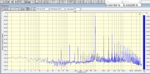
I started measurements with 1kHz tone at 1W (I used 8 ohm output loaded with 8 ohm high power resistors for almost all my measurements). With feedback at lowest setting THD is about 0.34% mostly from 2nd harmonic (See Pic.3). All other harmonics are much lower and spectrum shows classic triode exemplifier pattern when each higher order harmonic is smaller than lower one. That usually correlates with clean perceived sound. From noise perspective, highest component is 120Hz at about -70dB level. You can hear that when put ear close to speaker, but not from listening position. Of cause with very sensitive speakers you will have less luck, but then you will likely use a different amplifier. When I increased feedback to second level, distortion dropped to 0.24% and 120Hz hum component dropped 6dB down (Pic.4). Feedback clearly does its job to reduce distortion and noise.
At 5W the overall picture is the same with 2nd harmonic highest and higher harmonics all trending down (Pic.5). But at 10W (Pic.6) 3rd harmonic is equal 2nd and now highest is 4th. This is what you are dealing with getting into class A2. Again applying feedback (Pic.7) drops distortion, though keeping its pattern, and noise. For comparison I show distortion spectrum from amplifier with 845 tube running in class A1 without feedback (Pic.8). There distortion is higher, but pattern is still the same as at lower power. It keeps that pattern up to the point of clipping.
But with 805 tube we see that higher order harmonics are higher, and 4th is playing a very important role. That results in perceived sound differences between class A1 and class A2 triode amplifiers.
At 20W (Pic.9 for low feedback and Pic.10 for some feedback) we getting above what is possible while staying in A1 class. Here we again see that 2nd harmonic is the highest, and 4th is a second to it. Overall distortion is still relatively low, especially with some feedback used.
At 30W (Pic.11) third harmonic is again equal to 2nd, but we clearly see a picket of high order harmonics. Feedback (Pic.12), helps but not much. Amplifier is a on verge of clipping.
>>>Continues below<<<
After few days I took the amplifier from my listening room and put it on my work bench. There was time to measure and try to improve the sound. On a side I entered circuit into computer Spice simulator (I use MicroCap 12) which allows me to experiment with circuit adjustment before taking soldering iron and thus save the time by avoiding non-workable changes. For measurements I use EMU-0404USB audio interface, which despite being 10 years old is still the best D/A and A/D interface under $500. I use SpectraPlus SC, which allows all kinds of measurements utilizing standard ASIO capable interface. I had to make a special 20:1 balanced probe to allow me measure amplifier output, which can reach 20 V RMS or even more. I also checked shape of signal in circuit with Siglent SDS 1104X-E oscilloscope. For measuring at high voltages I have 100:1 probe that can handle over 1kV. I have an active balanced probe which I tried otuse, but found it unusable for audio measurements due to high level (-60dB) of spurious noises. That is why I had to make my own balanced probe for EMU, for its balanced XLR input.
Despite all my efforts to minimize the noise level in measurement chain, it still picked up something that was not at the amplifier output. But generally I was comfortable with measurement results. Though on spectrum plots you can see some things which should not really be there. At some day I will by Audio Precision gear for my home lab, but today I cannot justify that investment with amount of work I do in audio.
I started measurements with 1kHz tone at 1W (I used 8 ohm output loaded with 8 ohm high power resistors for almost all my measurements). With feedback at lowest setting THD is about 0.34% mostly from 2nd harmonic (See Pic.3). All other harmonics are much lower and spectrum shows classic triode exemplifier pattern when each higher order harmonic is smaller than lower one. That usually correlates with clean perceived sound. From noise perspective, highest component is 120Hz at about -70dB level. You can hear that when put ear close to speaker, but not from listening position. Of cause with very sensitive speakers you will have less luck, but then you will likely use a different amplifier. When I increased feedback to second level, distortion dropped to 0.24% and 120Hz hum component dropped 6dB down (Pic.4). Feedback clearly does its job to reduce distortion and noise.
At 5W the overall picture is the same with 2nd harmonic highest and higher harmonics all trending down (Pic.5). But at 10W (Pic.6) 3rd harmonic is equal 2nd and now highest is 4th. This is what you are dealing with getting into class A2. Again applying feedback (Pic.7) drops distortion, though keeping its pattern, and noise. For comparison I show distortion spectrum from amplifier with 845 tube running in class A1 without feedback (Pic.8). There distortion is higher, but pattern is still the same as at lower power. It keeps that pattern up to the point of clipping.
But with 805 tube we see that higher order harmonics are higher, and 4th is playing a very important role. That results in perceived sound differences between class A1 and class A2 triode amplifiers.
At 20W (Pic.9 for low feedback and Pic.10 for some feedback) we getting above what is possible while staying in A1 class. Here we again see that 2nd harmonic is the highest, and 4th is a second to it. Overall distortion is still relatively low, especially with some feedback used.
At 30W (Pic.11) third harmonic is again equal to 2nd, but we clearly see a picket of high order harmonics. Feedback (Pic.12), helps but not much. Amplifier is a on verge of clipping.
>>>Continues below<<<
Attachments
-
 Pic.8-845-1kHz-10W.PNG252.6 KB · Views: 85
 -
 Pic.7-1kHz-10W-FB2.PNG252.1 KB · Views: 82
 -
 Pic.6-1kHz-10W-FB1.PNG238.7 KB · Views: 73
 -
 Pic.5-1kHz-5W.png181.9 KB · Views: 391
 -
 Pic.4-1kHz-1W-FB2.PNG241.8 KB · Views: 393
 -
 Pic.3-1kHz-1W-FB1.PNG227.5 KB · Views: 390
 -
 Pic.10-1kHz-20W-FB2.PNG253 KB · Views: 76
 -
 Pic.9-1kHz-20W-FB1.PNG238.5 KB · Views: 88
 -
 Pic.11-1kHz-30W-FB1.PNG246.4 KB · Views: 86
 -
 Pic.12-1kHz-30W-FB2.PNG258.4 KB · Views: 93
Last edited:
>>>Continues here<<<
At 39W amplifier reached 10%THD (Pic.13) and applying feedback (Pic.14) does not help at all. Feedback is NOT a solution when amplifier already clipped. Pic.15 shows how output looks on oscilloscope at that moment. Thus we are 9W short from official power output. But I didn’t keep line voltage at 220V as it should be. When I measured it, it was 210-215V. That could affect the result. But in any way, 10% distortion is NOT a point where you should use amplifier. But real power with distortions below 5% is somewhere in 30-35W range. This is still twice more than usable power from A1 class amplifier (around 18W).
When I measured THD vs. Frequency, I noticed that when use lowest feedback, it is relatively flat with little raise at low and high parts of audio band. But when I apply feedback, although distortion in mid-range gets lower, at low and high frequencies distortions raise to much higher level. This is a trade off from using feedback. That may explain why many prefer low or no feedback amplifiers, even though they have higher THD on paper (which is usually measured at mid-range). Pic.16 and Pic.17 show THD vs Frequency at 30W with lowest and second from lowest feedback settings.
This amplifier has relatively high level of IMD, if measured with equal 19 and 20kHz tones. Even at 1W IMD is close to 1% (Pic.18), and applying feedback does not improve picture much. I suspect that this is because of slow slew rate that causes increased distortions at high frequencies.
I also did IMD measurements using 60Hz/7kHz 4:1 signal. That gave more reasonable results (Pic.19) at 20W. Pic.20 and Pic.21 show distortion components around 7kHz point with lowest and some feedback respectively. You can see that though feedback reduces distortion component amplitude, it also broadens the spectrum by adding higher order components (but they are low in level).
Considering that I had to use feedback to get acceptable bass, I measured output impedance. The results was 6 ohms at 8 ohm output and lowest feedback. When I increased feedback a notch, impedance reduced to 3.5 ohms. Of cause when I use 4 ohm output, this value is lower again. When I tried to use 8 ohm load from 4 ohm output, distortion at low level reduced a bit, but clipping condition occurred at power of less than 30W. Though clipping with 4 ohms load at 4 ohms output occurred at around 40W. It means that for best results one needs to use proper output that matches speakers.
>>>Continues below<<<
Attachments
-
 Pic.19.-IMD-60-7-20W-FB1.PNG243.8 KB · Views: 92
 -
 Pic.18-IMD-19-20-1W-FB1.PNG243.7 KB · Views: 91
 -
 Pic.17-THD-F-30W-FB2.PNG116 KB · Views: 70
 -
 Pic.16-THD-F-30W-FB1.PNG120.8 KB · Views: 82
 -
 Pic.15-SDS00001.png18.2 KB · Views: 102
 -
 Pic.14-1kHZ-17.8V-FB2.PNG264.9 KB · Views: 77
 -
 Pic.13-1kHz-17.7V-10%-FB1.PNG248.5 KB · Views: 86
 -
 Pic.21-IMD-60-7-20W-FB1-zoom.PNG132.4 KB · Views: 97
 -
 Pic.20-IMD-60-7-20W-FB2-zoom.PNG123 KB · Views: 79
>>>Continues from above<<<
Feedback settings also influence how amplifier handles high frequencies. When set to lowest feedback low and high frequencies are rolled off a bit reaching -2dB at 20Hz and -3dB at 20kHz. With feedback set to second level response is effectively flat between these two frequencies. (Pic.22). When I increased feedback further, I observed a slight bump centered around 25kHz. Amplifier does not have any feedback compensation and this bump is likely a result of limited stability margin. It is possible to add frequency/phase compensation in the feedback loop, but it won“t work very well with simple variable feedback setup. Square wave response is also changes with raise of feedback. At lowest level fronts are not as sharp, but increase of feedback causes overshoot and some ringing. Pic.23 shows square wave response at 1kHz and lowest feedback. Pic.24 and 25 show response at 1 and 10kHz with second feedback setting. Clear seen ringing appeared when I tried feedback at 3rd and 4th level. That is why I stopped at second feedback level for all other measurements and listening sessions.
Now after I had baseline measurements, it was time to try improve circuit. There are two things I could do: first was to try use different tube brands and select one that works better, second was to change circuit trying to reduce inherent distortion. For that purpose I created a circuit that mimics first two stages of amplifier on breadboard. There I could easily try different things before making any changes in the guts of LM-508ia.
I has some 6SL7 and 6SN7 tubes on hand and also ordered vintage Russian 1578 and 1579 tubes made in 1950s for Russian nuclear energy program and apparently highly rated by audiophiles. It took 3 weeks to get them from seller in Moscow. When I started using breadboard I quickly found that the set of tubes which came with LM has THE LOWEST distortion level from all combinations of tubes I had on hands. When running at levels required to drive output stage of LM-518ia, the distortion level from first two stages was between 1% and 1.25%. This is much lower than 5-10% observed in measurements at output of amplifier. That means output stage is the only real source of distortions in LM-518ia.
Nevertheless I tried two things. First I replaced load resistor for 6SL7 tube with CCS circuit using IXYS 10M90S, just like I did in 845 based amplifier (see reference in the beginning of this article). That increased gain and reduced distortion somewhat. But gain now was too high and real linearity improvement was only when I removed capacitor from cathode of 6SL7. Even then gain varied with frequency too much. At plate voltage swing needed to clip second stage (around 14 volts), advantage from CCS use was too small to justify that change. This is unlike 845 amplifier when single gain stage was used to provide full voltage swing for output tube close to 300 volts.
Next was to increase current though 6SN7 tube. In LM-518ia both triodes inside tube are paralleled. From old RCA tube manual recommended current through 6SN7 tube is 4mA. Here the TOTAL current was 4mA though both triodes inside the tube. Increasing the current potentially could improve handling of higher frequencies. Measurements at breadboard were promising and I tried that in real amplifier, by changing plate and cathode resistor in one of channels only. What I found was that overall distortion level does not improve much (only less than 0.5% better at 30W). At least using just a bit feedback made much more pronounced distortion reduction at midrange frequencies. High frequencies distortion didn’t really improved. But surprisingly distortion at very low (under 40Hz) frequencies were a bit lower with higher current through tube. But a side effect was higher distortion very close to clipping level. The same was when I removed bypass capacitor from cathode of 6SN7. In that case distortion profile changed with odd order harmonics getting higher at lower power.
I tried different combinations, but original schematic always gave me most balanced result. It looks like designers of this amplifier squeezed everything they could from the circuit and used some per-distortion tricks when per-amp gain stage distorts signal the opposite way to how power stage adds its distortion and overall distortion gets lower.
The last thing to try was simply to replace some components with better quality. This amplifier uses 0.1uF PP type capacitors between gain stages — total 3 of them in signal chain. They are already of good quality and I left them intact. Line Magnetic uses Nichicon capacitors exclusively in this amplifier. Cathode bypass capacitors are FW model, which is declared «Standard Audio» type. I had two supposedly better quality capacitors on hand: Nichicon Muse and Elna Silmic II. Considering that 6SL7 stage should have highest influence on the sound, I installed Silmic capacitors there and Muse capacitors in 6SN7 stage. I ran distortion measurements again, but didn’t find any difference. I also added 1uF PP capacitor in parallel with C101 capacitor in each channel. I used Panasonic brand capacitor for that.
I also did some adjustment of VU meters in the amp. I found that they are not really a dB calibrated meter. They react on PEAK rather than RMS voltage. They are also designed the way that «-2dB» mark is a MAXIMUM value they can show. Even when output RMS voltage increased above that point, they stayed at -2dB mark. I suspect the root cause of that is a zenner that clamps meter at +/- 12.4V (see schematic). It is very hard to remove meter board to replace zenner with higher value. The only thing I did was to adjust meter so that it shows -6dB at 10W output power.
With all that done, I brought amplifier back to my music room and started extensive listening. First I didn’t exactly liked the sound. But after few days it became cleaner. Likely components parameters drifted a bit to where they should be. That could happen with new components and mostly pronounced with tubes and electrolytic capacitors. Sign of that was a little drift of idle current of power tubes. I had to adjust it a bit after several days of listening. Then is became stable and didn’t require any further adjustments.
Overall the sound of LM-518ia is something between SET and push pull tube amplifiers. It does have very clean midrange, especially on acoustic music. Bass is more solid than with no-feedback amplifiers and sometimes punchy enough to feel it as vibration of the sofa I sit on. That was a good surprise from SET amplifier. With my speakers it plays loud enough for classic rock music peaking at 98dbC at my seat in music room. That is not concert level, but sufficient to enjoy most kinds of music. Of cause I can alway fire up my 300W Bryston, if I need more. I also noticed that this amplifier makes digital records (CDs) sound more like vinyl. That could be an advantage for some listeners. So far I am happy with purchase and will likely sell my old 845 amplifier and keep Line Magnetic in its place.
Considering the results, I would call LM-518ia a solid, high quality amplifier. Anyone who wants SET setup and has lower sensitivity speakers, can try it and most likely won't be disappointed. Purchase directly from China is no brainier, when US and Europe based dealers ask two times more money for exactly the same unit (the only difference for US users is 120V vs 220V main power).
>>>THE END<<<
Attachments


You may find that the amp makes its rated power with old stock 838s. When I have messed with similar circuits, I'd see less than 25W with Shuguang 805A where an 838 would make 30W.
You may find that the amp makes its rated power with old stock 838s. When I have messed with similar circuits, I'd see less than 25W with Shuguang 805A where an 838 would make 30W.
It is very possible. But it is not easy to find NOS 805 or 838 tubes for a reasonable price. I do not want to spend $1000+ on tubes.
As a side note, I tried to use Sophia Princess 300B tubes in driver stage, but didn't like them at all. They made sound too "sweet". Stock tubes gave more transparent presentation, even more so after capacitors change.
Used 838s aren't all that expensive.
Yes, the 300B cathode follower is a marketing choice, not a design choice.
Yes, the 300B cathode follower is a marketing choice, not a design choice.
>>>Continues from above<<<
Feedback settings also influence how amplifier handles high frequencies. When set to lowest feedback low and high frequencies are rolled off a bit reaching -2dB at 20Hz and -3dB at 20kHz. With feedback set to second level response is effectively flat between these two frequencies. (Pic.22). When I increased feedback further, I observed a slight bump centered around 25kHz. Amplifier does not have any feedback compensation and this bump is likely a result of limited stability margin. It is possible to add frequency/phase compensation in the feedback loop, but it won“t work very well with simple variable feedback setup. Square wave response is also changes with raise of feedback. At lowest level fronts are not as sharp, but increase of feedback causes overshoot and some ringing. Pic.23 shows square wave response at 1kHz and lowest feedback. Pic.24 and 25 show response at 1 and 10kHz with second feedback setting. Clear seen ringing appeared when I tried feedback at 3rd and 4th level. That is why I stopped at second feedback level for all other measurements and listening sessions.
Now after I had baseline measurements, it was time to try improve circuit. There are two things I could do: first was to try use different tube brands and select one that works better, second was to change circuit trying to reduce inherent distortion. For that purpose I created a circuit that mimics first two stages of amplifier on breadboard. There I could easily try different things before making any changes in the guts of LM-508ia.
I has some 6SL7 and 6SN7 tubes on hand and also ordered vintage Russian 1578 and 1579 tubes made in 1950s for Russian nuclear energy program and apparently highly rated by audiophiles. It took 3 weeks to get them from seller in Moscow. When I started using breadboard I quickly found that the set of tubes which came with LM has THE LOWEST distortion level from all combinations of tubes I had on hands. When running at levels required to drive output stage of LM-518ia, the distortion level from first two stages was between 1% and 1.25%. This is much lower than 5-10% observed in measurements at output of amplifier. That means output stage is the only real source of distortions in LM-518ia.
Nevertheless I tried two things. First I replaced load resistor for 6SL7 tube with CCS circuit using IXYS 10M90S, just like I did in 845 based amplifier (see reference in the beginning of this article). That increased gain and reduced distortion somewhat. But gain now was too high and real linearity improvement was only when I removed capacitor from cathode of 6SL7. Even then gain varied with frequency too much. At plate voltage swing needed to clip second stage (around 14 volts), advantage from CCS use was too small to justify that change. This is unlike 845 amplifier when single gain stage was used to provide full voltage swing for output tube close to 300 volts.
Next was to increase current though 6SN7 tube. In LM-518ia both triodes inside tube are paralleled. From old RCA tube manual recommended current through 6SN7 tube is 4mA. Here the TOTAL current was 4mA though both triodes inside the tube. Increasing the current potentially could improve handling of higher frequencies. Measurements at breadboard were promising and I tried that in real amplifier, by changing plate and cathode resistor in one of channels only. What I found was that overall distortion level does not improve much (only less than 0.5% better at 30W). At least using just a bit feedback made much more pronounced distortion reduction at midrange frequencies. High frequencies distortion didn’t really improved. But surprisingly distortion at very low (under 40Hz) frequencies were a bit lower with higher current through tube. But a side effect was higher distortion very close to clipping level. The same was when I removed bypass capacitor from cathode of 6SN7. In that case distortion profile changed with odd order harmonics getting higher at lower power.
I tried different combinations, but original schematic always gave me most balanced result. It looks like designers of this amplifier squeezed everything they could from the circuit and used some per-distortion tricks when per-amp gain stage distorts signal the opposite way to how power stage adds its distortion and overall distortion gets lower.
The last thing to try was simply to replace some components with better quality. This amplifier uses 0.1uF PP type capacitors between gain stages — total 3 of them in signal chain. They are already of good quality and I left them intact. Line Magnetic uses Nichicon capacitors exclusively in this amplifier. Cathode bypass capacitors are FW model, which is declared «Standard Audio» type. I had two supposedly better quality capacitors on hand: Nichicon Muse and Elna Silmic II. Considering that 6SL7 stage should have highest influence on the sound, I installed Silmic capacitors there and Muse capacitors in 6SN7 stage. I ran distortion measurements again, but didn’t find any difference. I also added 1uF PP capacitor in parallel with C101 capacitor in each channel. I used Panasonic brand capacitor for that.
I also did some adjustment of VU meters in the amp. I found that they are not really a dB calibrated meter. They react on PEAK rather than RMS voltage. They are also designed the way that «-2dB» mark is a MAXIMUM value they can show. Even when output RMS voltage increased above that point, they stayed at -2dB mark. I suspect the root cause of that is a zenner that clamps meter at +/- 12.4V (see schematic). It is very hard to remove meter board to replace zenner with higher value. The only thing I did was to adjust meter so that it shows -6dB at 10W output power.
With all that done, I brought amplifier back to my music room and started extensive listening. First I didn’t exactly liked the sound. But after few days it became cleaner. Likely components parameters drifted a bit to where they should be. That could happen with new components and mostly pronounced with tubes and electrolytic capacitors. Sign of that was a little drift of idle current of power tubes. I had to adjust it a bit after several days of listening. Then is became stable and didn’t require any further adjustments.
Overall the sound of LM-518ia is something between SET and push pull tube amplifiers. It does have very clean midrange, especially on acoustic music. Bass is more solid than with no-feedback amplifiers and sometimes punchy enough to feel it as vibration of the sofa I sit on. That was a good surprise from SET amplifier. With my speakers it plays loud enough for classic rock music peaking at 98dbC at my seat in music room. That is not concert level, but sufficient to enjoy most kinds of music. Of cause I can alway fire up my 300W Bryston, if I need more. I also noticed that this amplifier makes digital records (CDs) sound more like vinyl. That could be an advantage for some listeners. So far I am happy with purchase and will likely sell my old 845 amplifier and keep Line Magnetic in its place.
Considering the results, I would call LM-518ia a solid, high quality amplifier. Anyone who wants SET setup and has lower sensitivity speakers, can try it and most likely won't be disappointed. Purchase directly from China is no brainier, when US and Europe based dealers ask two times more money for exactly the same unit (the only difference for US users is 120V vs 220V main power).
>>>THE END<<<
May I suggest that you change R110 to 2 watt AB 1K resistor
Nope but it improves the sound, proof of the pudding it's been tested on this very same amp.
Cheers
Cheers
May I suggest that you change R110 to 2 watt AB 1K resistor
I can try to reduce the value. It may improve HF response a bit.
Actually radical change could be to use 8 to 16 ohms section of output transformer for cathode local feedback. I know some designers did this with 805 tube. Though it would require move of global feedback from first to second gain stage. That will make final stage a bit linear on its own. And I can use CCS for 6SL7 to compensate of removal of it from GNF loop.
Used 838s aren't all that expensive.
Yes, the 300B cathode follower is a marketing choice, not a design choice.
Actually 300B is a reasonable choice here. It dissipates significant power on its own. And this is probably the only 40W power triode currently in production in China. In this circuit it indeed dissipates close to 40W at idle.
The 300B contributes a fair amount to noise and doesn't have all that much Gm. An EL34 or EL84 would be a stout cathode follower, or the obvious choices like 6080, 6AS7, 5998.
For feedback, local works but is a PITA to design. Keeping the OT out of the loop is very helpful.
For feedback, local works but is a PITA to design. Keeping the OT out of the loop is very helpful.
The 300B contributes a fair amount to noise and doesn't have all that much Gm. An EL34 or EL84 would be a stout cathode follower, or the obvious choices like 6080, 6AS7, 5998.
For feedback, local works but is a PITA to design. Keeping the OT out of the loop is very helpful.
In this circuit you need not only enough current, but some voltage swing too. Most tubes you mentioned may have the problem with that.
I will try to simulate other tubes in the circuit to see if there is any improvements in distortion figures.
As to the noise - when I removed tubes from pre-amp stage, there was almost nothing coming from speakers.
The 300B in this circuit provides no voltage gain. You won't suddenly limit the voltage provided to the 805 by using something else there.
The peak current demand from the directly coupled cathode follower is rather high, and I would expect that there are some better performers in this position than the 300B.
The peak current demand from the directly coupled cathode follower is rather high, and I would expect that there are some better performers in this position than the 300B.
The 300B in this circuit provides no voltage gain. You won't suddenly limit the voltage provided to the 805 by using something else there.
The peak current demand from the directly coupled cathode follower is rather high, and I would expect that there are some better performers in this position than the 300B.
These could be some tubes which work a bit better. But keep in mind that LM could not use tubes which are not in current production.
There is also a possibility to replace load resistor for CF with CCS. There some pentode will be in place.
EL34/84 are in production. For the number of these amps that they are selling, using 6AS7s would hardly be problematic.
Cathode followers that use Indirectly Heated tubes:
The peak to peak Cathode voltage swing is limited by the maximum filament to cathode voltage ratings.
Cathode followers that use Directly Heated Triodes:
The peak to peak filament voltage swing is limited by the maximum filament to grid voltage rating, and also the maximum plate to filament voltage rating.
Do you see the difference?
(in some cases 100 to 200V peak to peak difference between DHT and Indirectly Heated tubes).
That is a lot!
Last edited:
- Home
- Amplifiers
- Tubes / Valves
- Line Magnetic LM-508ia - Affordable high power SET amplifier