Hi, Trying to repair an linn powertex amplifier, two of the output transistors were blown, these are now replaced, and I have no DC leaking out on the
speaker terminals now. The white ceramic resistors are all measuring ok. I am still have a few issues, sometimes motorboating sound, Which disappear when the amplifier is turned off (and it plays for a few seconds due to power in the filter caps) So I suspect decoupling between the power supply and audio, I have it on a bulb tester and my bulb is not lighting so no shorts. Attached files, on the power lines is one supposed to be an ztx753 (pnp) and the other an ztx653 (CBE config ) (npn)? as both are labelled as pnp. Not sure If I can post the whole diagram here? it was released by Linn. My powerlines seem to be around the +25 and -25Volts (true RMS with negative on transformer negative supply - centre tap....chassis does not seem to be earthed) on the bulb tester, and do not fluctuate when the motorboat noise is there. All the electrolytic caps are fine. I have replaced the smaller ones (only a few), they did all measure ok under no load conditions. (polarity is fine, issue was there before recap) I have gone through each transistor in circuit with a diode tester and they seem ok, all diodes tested good, not sure on zenor what voltages I should have there D411 & d412 on either ends ? . Any hints what to look for, thanks in advance
speaker terminals now. The white ceramic resistors are all measuring ok. I am still have a few issues, sometimes motorboating sound, Which disappear when the amplifier is turned off (and it plays for a few seconds due to power in the filter caps) So I suspect decoupling between the power supply and audio, I have it on a bulb tester and my bulb is not lighting so no shorts. Attached files, on the power lines is one supposed to be an ztx753 (pnp) and the other an ztx653 (CBE config ) (npn)? as both are labelled as pnp. Not sure If I can post the whole diagram here? it was released by Linn. My powerlines seem to be around the +25 and -25Volts (true RMS with negative on transformer negative supply - centre tap....chassis does not seem to be earthed) on the bulb tester, and do not fluctuate when the motorboat noise is there. All the electrolytic caps are fine. I have replaced the smaller ones (only a few), they did all measure ok under no load conditions. (polarity is fine, issue was there before recap) I have gone through each transistor in circuit with a diode tester and they seem ok, all diodes tested good, not sure on zenor what voltages I should have there D411 & d412 on either ends ? . Any hints what to look for, thanks in advance
Attachments

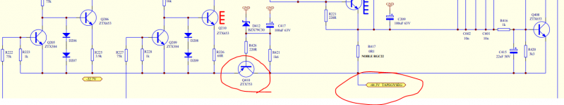
I also noticed on the power supply circuit for the transistors they have the ZTX753 (E-LINE MINIPLAST) listed as EBC, the new ones I have tested as being CBE on transistor tester, did they use some different Japanese version? Or is the diagram wrong? I guess I will have to pull a known good one out and test it
Ok they are CBE and error on the diagram, so my voltages on both positive and negative rails are good, the voltage between collector + emitter on Q208 is good at 1.25volts. It plays fine on both sides a very low volume, if you crank the pre at all both sides are distorted. Can I pull R215 NFB Resistor to see if its the feedback circuit introducing the distortion, I do not have a scope, but a signal tracer (not great a picking up the distortion)
At Diode d409 on right hand side of diagram I have -26.54 and -25.6V at cathode. This goes to R-channel 75k ? where does this go? I thought the output is RSS?
You are not getting much help. You've been answering yourself, which makes others ignore the thread.
You've done well to check the power supplies that they are not varying voltage when the motorboating occurs.
Usually one checks at various points through the circuit to see the first place that the motorboating occurs. Then you look for problems in that area. Could be a component breaking down, could be a flux path from one trace to another leaking periodically. A DVM is not much use for tracing this, they average voltage over 2 to 4 seconds. The cheapest alternative to a scope is an analog VOM with a 20 vac scale, and if you can afford it, a 2 vac scale for the input stage. Often available for $35 or so. When measuring AC, put a .047 uf cap of voltage rating double the power supply series the ground probe to keep the AC scale from showing readings on DC voltage. I've had analog Voltmeters respond as fast as 60 hz , one $6 Radio Shack model vibrated near full scale when plugged into the AC wall socket on 200 vdc scale.
Your transistor tester tests at 2 volts or less, and won't show voltage breakdown. Same with capacitor testers. You need to test for repetitive shorting buy measuring current into a suspect part at near the voltage it is biased by in circuit. Capacitors charged by a resistor, the test is simple, look at DC voltage at the junction to see if it is the source of the motorboating.
I have to say, I don't understand the function of Q801 Q802 and all that at the right of the diagram.
Hi thanks for your reply, I was looking into buying a scope, i will get one soon, I just installed trueRTA on an old windows xp computer with a good soundcard (m-audio 2496) and have a probe with variable gain made up. I injected a 1khz sinewave and already see the sine wave on collector and emitter on q208 clipping, I am going to try and lift one side of the negative feedback resistor R215 / r315 both channels and see what happens I want to rule out the feedback. Good idea the cap on the ground lead I will try that. The only AC measuring is before the bridge rectifier, so will try that and see that positive and negative supply remains steady.
Got is sorted, got there in the end, I had given up on this several times. Much easier to find components completely dead than intermittent
Did something go wrong with your post #8 above? It would be good to know just what you found and how you sorted the problem.
Hi, not sure what you mean about something wrong with post 8 ? I got it fixed, I had measured each diode, transistor several times and all measured ok with just a multimeter, transistor tester, i.e. under no load. Decided to replace all the diodes (except the zenor) and it worked. Think there were about 18 or so, only took 30mins. Just lucky it was not one of the transistors, as that would have taken a lot longer. Ran it for several hours and its been working away fine, its a very neutral amplifier, not as much power as my arcam alpa 10's but a good little amp all the same.
- Home
- Amplifiers
- Solid State
- Linn Powertek