Simple circuits to reduce noise of common LM78xx voltage regulators.


Updates:
1. Turns out that LM7805 doesn't start up reliable in this configuration, and thread name difficult to change. It happens if 5 * Iq rules is broken, so there is another version:

2. Basic concept, that helps to understand role of a regulator as "pass element"

Some test results with 3v3 and 5v6 zeners:


Scale is referenced to 3 nV-rms at -140 dB line.
So the best performance I've got so far using lm7805 & 5v6, about 7 nV-rms. It's interesting, as I know that 5.6V zener noisier than 3v3, but high dynamic resistance of 3v3 (70 Ohms vs 5 Ohms) limits the gain of bjt. Option may be to use 2 bjt or some OPA, if I decide to push noise down.
Updates:
1. Turns out that LM7805 doesn't start up reliable in this configuration, and thread name difficult to change. It happens if 5 * Iq rules is broken, so there is another version:
2. Basic concept, that helps to understand role of a regulator as "pass element"
Some test results with 3v3 and 5v6 zeners:
Scale is referenced to 3 nV-rms at -140 dB line.
So the best performance I've got so far using lm7805 & 5v6, about 7 nV-rms. It's interesting, as I know that 5.6V zener noisier than 3v3, but high dynamic resistance of 3v3 (70 Ohms vs 5 Ohms) limits the gain of bjt. Option may be to use 2 bjt or some OPA, if I decide to push noise down.
Last edited:

Can you provide a explanation of the working principle behind the added circuit. I'm guessing there is added gain in the feedback loop? I understand that some LED's can be used in place of a Zener diode as they may have lower noise.
Explanation.
LM78xx includes 3 basic functions:
- voltage regulation;
-overtemperature protection;
-overcurrent protection.
First one -regulation is not perfect, and much noisier than common zener diode.
So concept is to delegate voltage regulation subfunction to zener+BJT circuits, leaving another 2 sub functions to LM78xx. IC plays a role "pass element", transistor can do same thing but designing OCP OTP 'd be necessary.
I tested TZX5V6D and BZX55B3V3 and can say that TZX5V6D performs better, since dynamic resistance much lower.
Same apply to LED's., all depends on part number.
Diego has provided 78xx compatible versions of the denoiser:
 It is just a random example in huge thread, but there are others
Possibly, this can be a universal form of the "Fixnoiser" for output voltages from 5 to 24 V 😉.
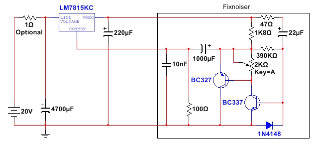
Definitive! And it also supresses noise. I did not expect that actually.added gain in the feedback loop
Active feedback is a challenge. Only for the bold & courageous.
I'll look that up!Diego has provided 78xx compatible versions of the denoiser:
Response to #4.
I see. My approach is different, despite some similarities.
What I notice making quick review of the thread , that they have to use a resistance in series with a load, 15-47 or like that. If author was hoping to null-out noise w/o touching DC accuracy, than he failed. Voltage drop across resistance IS a dc error. Since lm317 & basically any V.regulator are very low output impedance devices, there is no way to reduce noise by suppression using external amp - required power level is too high, and some series R required in any case.
My circuits declines DC accuracy right away, as out of priority list. Keeping output impedance as low as it was advertised in DS for specific V.regulator by manufacturer.
I don't use any adjustments, potentiometers etc.
No huge electrolytics.
they have to use a resistance in series with a load, 15-47
No, only the Wenzel circuit requires it. Diego's approach uses a resistor in series with the GND pin, but that's of no consequence
There is, DC error = ~5mA (I-q) x 100 Ohm = 500 mV, 7815 becomes 15.5V.approach uses a resistor in series with the GND pin, but that's of no consequence
What is more important, I-q depends on V-in (look into DS), and it means Line Regulation parameter is degraded.
The GND current will indeed cause a small error, and that error won't be constant: it depends on the output current and the dropout voltage, but what matters is the variation: around 0.7mA for a reasonable set of conditions.
0.7*100=70mV. Not negligible, but not catastrophic either.
Now, let's look at your circuit:
The 5V6 zener cannot be conducting, otherwise it will shunt the correction signal to the ground.
If it doesn't conduct, the voltage on the collector of the transistor will depend on the equilibrium between the collector current and the GND pin current.
The collector current will increase steeply as soon as the image of the output voltage reduced by the resistive divider reaches ~3.3+1Vbe, thus values appearing on your sim.
Problem, a 3v3 zener has a negative tempco, as has the Vbe.
This means that the output voltage will have a strong negative tempco, and will be loosely defined due to the balance between the collector current and the GND pin current.
Chose your evil and ask the opinion of @diegomj1973 ....
Right, it's not. But DC accuracy is ruined, none of the parameters specified in DS are not relevant since all spec. tested W/O any resistor in series with ground .The GND current will indeed cause a small error, and that error won't be constant: it depends on the output current and the dropout voltage, but what matters is the variation: around 0.7mA for a reasonable set of conditions.
0.7*100=70mV. Not negligible, but not catastrophic either.
So here is the question: why spend resources on more complex and costly circuits if both approaches are not DC accurate?
My circuits, as I already say has priority for noise reduction, well and cost/ simplicity.
Zener 5V6 for start-up only. Posted circuits is not working with LM7805 regulators at this time, since I discovered starting reliability issue. Will update OP later on.The 5V6 zener cannot be conducting, otherwise it will shunt the correction signal to the ground.
You are free to worship any circuits you like, I don't.Chose your evil and ask the opinion of @diegomj1973 ....
The circuit I proposed is not mine: it is from Diego. I am an outsider, and I judge each circuit on its merits. Yours is interesting, but it has its weaknesses. Same for Diego's take.
The circuit I proposed was the original denoiser, which also brings ~30dB improvements on all key parameters and doesn't compromise any DC characteristics.
It is not perfect either: it only works for adjustable regulators like the 317, and requires a significant settling time.
Life is made of tradeoffs....
I have included your circuit in the broad index of denoising circuits:
If you object to it, I'll remove it and you can enrich your own thread on the subject
Edit:
The index can be found here:
Simple circuits to reduce noise of common LM78xx voltage regulators.
Updates:
1. Turns out that LM7805 doesn't start up reliable in this configuration, and thread name difficult to change. It happens if 5 * Iq rules is broken, so there is another version:
2. Basic concept, that helps to understand role of a regulator as "pass element"
Some test results with 3v3 and 5v6 zeners:
Scale is referenced to 3 nV-rms at -140 dB line.
So the best performance I've...
Edit:
The index can be found here:
D-Noizator: a magic active noise canceller to retrofit & upgrade any 317-based V.Reg.
✪ A simple circuit that transforms a good, clumsy workhorse like the LM317 into a superreg so easily that you do not even need to cut a single track. ✪
✪ It must be too good to be true.... or ✪
 .........................................................................................................................
 It's Christmas!!!


The present SOTA...✪ It must be too good to be true.... or ✪
......................................................................................................................... It's Christmas!!! I don't mind for indexing.
Just realize, that I probably use wrong thread name, as my concept works with any voltage regulators. Firstly I tried to de-noise AP7381-3.3, my favorite regulator in SD ADC evaluation. Than switch to 78xx.
LM317 is also in my list.
So far only LM2931 doesn't compatible with simplest circuits, due to stability issue.
- Home
- Design & Build
- Electronic Design
- LM78xx voltage regulator noise reduction by 30 dB