I have a Low Pass filter calculation that I couldn't solve, maybe one of y'all can figure it out, I couldn't. Neither could some of my colleagues.
So we have a two pole low pass filter. After the fc, the slope is -40dB decade. Also after the fc and at 1200Hz the output voltage is 4V.
What is the output voltage at 2400Hz?
There is Av = 20Log (Vout/Vin) is it:
-40dB = 20Log (Vout/4V)? 2log-1*4 = Vout? V = .8 @ 2400Hz
Cheers,
So we have a two pole low pass filter. After the fc, the slope is -40dB decade. Also after the fc and at 1200Hz the output voltage is 4V.
What is the output voltage at 2400Hz?
There is Av = 20Log (Vout/Vin) is it:
-40dB = 20Log (Vout/4V)? 2log-1*4 = Vout? V = .8 @ 2400Hz
Cheers,
There are an infinite number of 1200 Hz two pole lowpass filters. They differ in their quality factor "Q", the number of dBs of ripple in the passband, and the number of dBs of ripple in the stop band.
The most famous of these are (i) the Critically Damped filter; (ii) the Butterworth Alignment filter; (iii) the Bessel Alignment filter; (iv) the Chebyshev 1dB passband ripple filter.
Each of them has a -3dB amplitude response at 1200 Hz. Each of them has a slope of -40dB per decade, above 48 kHz. But each of them has a different amplitude response at 2400 Hz. You won't be able to calculate the answers to the questions in post #1, until you decide which two pole lowpass filter you are analyzing. Google for the four search phrases mentioned above, (i) ... (iv), to learn more.
Mark,
It would have to be along the Butterworth Alignment filter. Bessel and Chebyshev were ruled out, not sure about i.
If we are past the fc point and along the 40dB slope.... the 1200 Hz, 4V output is along that slope.
What would the output be at 2400 Hz?
or is this question seriously flawed?
It would have to be along the Butterworth Alignment filter. Bessel and Chebyshev were ruled out, not sure about i.
If we are past the fc point and along the 40dB slope.... the 1200 Hz, 4V output is along that slope.
What would the output be at 2400 Hz?
or is this question seriously flawed?
What would the output be at 2400 Hz? or is this question seriously flawed?
Even for a given filter like this Butterworth, the damping will affect the next octave. You need the actual equation or component values to determine the alignment. The unmarked frequency division is sqrt 10 (~3.16), more than an octave. https://www.st-andrews.ac.uk/~jcgl/Scots_Guide/audio/part3/fig8.gif
For a maximally flat first order Bode plot, rules of thumb for corrections to straight line approx: At the corner, response is -3dB; an octave higher is -1dB; factor of ten higher is -0.1dB. Second order is a little different.
Last edited:
40dB/decade is 12dB/octave so roughly speaking your 2.4kHz output is going to be 12dB lower than your 1.2kHz output. So 1V would be my answer.
It is a real pisser to have to deal with this stuff.
You can imagine my surprise when I responded that standard home light dimmers, are noisy, for low noise you want the variac in the wall type.
Know it all said, no they aren't noisy at all? and look at those initials...
Know It All - KIA - Killed In Action
Yes, Abraxilito, I think that is what I also found reference too. Standard single pole rolloff, 20 dB/decade = 6 dB/octave = 2x V. Double that double pole at 40 dB/decage = 12 dB/octave = 4x V. So 4V/4x = 1V out.
rayma - The older texts that I have discuss the w etc. That is the greek w. as in wave? Nope, angular frequency. W as in wagon?
I found it, but not how to pronounce it. Oh the Joy. : ) Link
That wasn't it either, but on this one I found it. it is Omega, the lower case letter shown at the right in the greek alphabet section. LINK
Cheers,
Last edited:
Yep, EE books are written by EEs, for an expected audience of EEs. These people get two and a half years (in a four year curriculum) of lectures about omega and phi and theta and zeta and so forth. It's not greek to them -- it's worldwide standard notation. It's in all the books. It's in all the lectures. It's burned into their brains.
A two-pole Butterworth low pass filter will have a response at twice the corner frequency of 1/sqrt(1+2^4) which is 1/sqrt(17). 4V in will give 0.97V out.
When you read the original post accurately, you see that the corner frequency is unknown, but < 1200 Hz. 4 V is not the input level, but the output level at 1200 Hz. So all in all, I think abraxalito's answer is the most accurate estimate - assuming that the unspecified input level is frequency independent, that is.
Last edited:
Yes, if all we know is that the corner is at or below 1200Hz (and the filter is 2-pole Butterworth) than all we can say is that 4V in at 2400Hz means somewhere between 0.97V and 1V out. As always, some context could help us answer the question which the OP might have meant to ask.
The older texts that I have discuss the w etc. That is the greek w. as in wave?
Nope, angular frequency. W as in wagon?
Omega is 2 x Pi x frequency (in Hertz). The units for omega are radians,
where 2 x Pi radians = 360 degrees, or 1 radian = 360/(2Pi), or about 57 degrees.
Yes, if all we know is that the corner is at or below 1200Hz (and the filter is 2-pole Butterworth) than all we can say is that 4V in at 2400Hz means somewhere between 0.97V and 1V out. As always, some context could help us answer the question which the OP might have meant to ask.
Actually, now that I think about it a bit better, it's even worse:
At 1200 Hz:
gain = DC gain / sqrt(1 + (1200 Hz/fc)^4)
At 2400 Hz:
gain = DC gain / sqrt(1 + (2400 Hz/fc)^4)
Ratio:
sqrt((1 + (2400 Hz/fc)^4)/(1 + (1200 Hz/fc)^4))
fc is known to be < 1200 Hz.
Limit of the ratio for fc -> 1200 Hz:
sqrt((1 + (2400 Hz/1200 Hz)^4)/(1 + (1200 Hz/1200 Hz)^4)) ~= sqrt(17/2) ~= 2.9154759
Limit of the ratio for fc -> 0 Hz:
sqrt((2400 Hz/fc)^4/(1200 Hz/fc)^4) =sqrt(2^4) = 4
Output voltage at 1200 Hz is 4 V, so assuming a frequency-independent input level, the output voltage at 2400 Hz can be anything between 1 V and 4/sqrt(17/2) ~= 1.372 V. When fc << 1200 Hz, it will be closer to 1 V than to 1.372 V.
I agree that some context would be nice, as I haven't a clue what this calculation is good for.
Last edited:
Ok, I misread it. 4V is the output at 1200Hz. I thought it was the input.
Maybe we should just say Vout = Vin/sqrt(1 + (f/fc)^4) - then let him work it out himself.
Maybe we should just say Vout = Vin/sqrt(1 + (f/fc)^4) - then let him work it out himself.
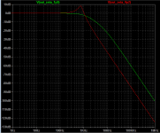
Here are two second order lowpass filters, see Figure 1.
Both have a -3dB corner frequency of 1150 Hertz. Just barely below 1.2 kHz. See Figure 2.
The filter plotted in green, has a quality factor Q of (1/3), namely a damping factor zeta of 1.50.
The filter plotted in red, has a quality factor Q of 2.5, namely a damping factor zeta of 0.20.
For the filter plotted in green, (Vout_2400_Hz / Vout_1200_Hz) equals -4.31 dB. A factor of 0.609. See Figure 3.
For the filter plotted in red, (Vout_2400_Hz / Vout_1200_Hz) equals -14.95 dB. A factor of 0.179. See Figure 4.
If Vout_2400_Hz = 4.0 volts, then Vout_1200_Hz is either 2.436 volts (green), or else 0.716 volts (red).
These results contradict the claim (in post #13) that
_
Both have a -3dB corner frequency of 1150 Hertz. Just barely below 1.2 kHz. See Figure 2.
The filter plotted in green, has a quality factor Q of (1/3), namely a damping factor zeta of 1.50.
The filter plotted in red, has a quality factor Q of 2.5, namely a damping factor zeta of 0.20.
For the filter plotted in green, (Vout_2400_Hz / Vout_1200_Hz) equals -4.31 dB. A factor of 0.609. See Figure 3.
For the filter plotted in red, (Vout_2400_Hz / Vout_1200_Hz) equals -14.95 dB. A factor of 0.179. See Figure 4.
If Vout_2400_Hz = 4.0 volts, then Vout_1200_Hz is either 2.436 volts (green), or else 0.716 volts (red).
These results contradict the claim (in post #13) that
the output voltage at 2400 Hz can be anything between 1 V and 4/sqrt(17/2) ~= 1.372 V.
_
Attachments


Don't know what either F nor Fc is.
For clarification, I asked a PhD in physics... the closest we came to was what we calculated in the first post.
I'm pretty sure now the correct answer is along the slope using the 20dB/decade = 6dB/octave (two times the Voltage). Where a two pole Butterworth is 40 dB/decade, 12dB/octave. (four times the Voltage). 4V/4 times = 1, therefore 1 V output at 2400.
One Volt it is. 🙂
The other calculations are close...so it should be 1V, I think.
Mark what did you use for the calculations? Recall we started at 1200 Hz, and 4 V out.
Both of these were after the Fc of the low pass filter. Presumably along the flat rolloff curve.
Last edited:
....After the fc, the slope is -40dB decade. Also after the fc and at 1200Hz the output voltage is 4V.
We are TOLD that the slope over the range of interest IS 40dB/Dec. I don't know if this is true (it rarely is), but this is a GIVEN. Apparently an abstract question, not a real-world problem.
40dB/Dec is same-as 12dB/Octave.
1200 to 2400 is one octave.
2400 will be 12dB down from 1200.
-12dB is 4:1. So at 1200 is 1V.
- Status
- Not open for further replies.
- Home
- Member Areas
- The Lounge
- Low Filter Roll Off Calculation