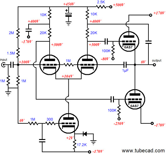
I am working on a second version of my OTL headphone amp that is build using a modified longtail phase splitter and two 6AS7G in push/pull. My new circuit resembles bot are not identical to this one form tube cad:
My phase splitter will be connected between ground and B+, with a BJT wilson current mirror as the current source. But I am in doubt of how low I can make B+ for it to be enough to drive the splitter.
As this is a redesign I would like to recycle the transformers from my PSU. With them I can either deliver a 200Vdc rail, by stacking 3 secondary windings, or I can connect one trans in reverse and make a 300Vdc rail.
I am considering using either 12AX7 or 12AU7 tubes for this application, where I would like to keep the voltages as low as possible for safety, budget and space. This amplifier is only meant to give a little more than unity gain, which is why im not sure which of the tubes I should choose and what B+ they will work with.
I will also need a negative bios voltage, that is lower than my supply rails, but what is the simplest way to make a low current bios voltage? My simulations estimate that I need a grid voltage of about -21V, but the bios voltage should of course be adjustable.
The bios from the top tube will be made with a standard voltage divider between a DC servo at GND and -65V. But the bottom tube is where I have my issue.
Last edited:
I do not know what your actual circuit will be, but the above schematic has no provision to insure that the output will be 0.0V.
It can have DC voltage out, both during warmup, and during operation after warm up.
It can have DC voltage out, both during warmup, and during operation after warm up.
That is true and that is some of the areas where my circuit differs from the one illustrated. I got a safety system in place that grounds the input and disconnects the output during startup and at over voltage and over current on the output. Plus the upper tube is controlled by a bias voltage that is adjusted from a DC servo, keeping the average output voltage at less than 10mV, according to the simulation.
My signal path however is quite close to the illustrated circuit, even though I use other values for caps and resistors. Like my 6as7g runs on a +-65V supply and not 170v.
My over all goal is to keep the voltages down while the sound quality is high. I wouldn’t feel safe while having potentially 500V on my ears.
A couple of years ago, my business partner witnessed a spectacular failure of an OTL tube amp involving several output tubes imploding and pieces of shattered ceramic Accuton woofer sent flying on one channel, fortunately nobody was injured.I am working on a second version of my OTL headphone amp that is build using a modified longtail phase splitter and two 6AS7G in push/pull. . . . .
I would suggest a more conventional common cathode tube amp topology with a step down transformer for headphone amp.
Some failure modes of a tube amp may generate a virtually instantaneous high energy destructive pulse. Should you insist on continuing with this design, the very least you should do is dig deeper on fast acting protection to insure safety of those using the amp. I don't think a relay is fast enough.
I do think that my safety system should be in order to protect my headphones. If we say that the wors case scenario is a tube that immediately shorts out, raising the output voltage to 65V, that would only result in a single very short pulse, before my output is disconnected.
My fault detection system is made with very fast gates and comparators, which brings the detection time to less than 1us. The relay has a release time of 3ms. This brings the total energy in the pulse, on my 70 ohm headphones down to way less than 1J.
E=(U^2*t)/R
E=(65^2V*3ms)/70ohm=0.181J or 0.181W if measured over 1s which is well within the power rating of my headphones.
So can we please get back to my questions regarding the phase splitter and the bios voltage?
The formula you should use is : P = U^2/R = 65^2/70 = 60.36W
Meaning power of 60.36W will be delivered to the tranducer for 3mS. Safe enough for a headphone? I would suspect a high probability of permanent hearing loss when an IEM is involved.
Now about your question.
- A 12AU7 should perform more linearly at lower B+ compared to the 12AX7 as shown here. Use simulation to determine required B+ and plate loading for operating condition you want.
- Negative 130V bias can easily be obtained using a voltage doubler from your 65V supply. Use voltage divider to adjust.
What is it you found to be an issue? State your questions, difficulties and considerations in a clear and specific manner.
There is plenty of methods to protect the output against transients, if needed I could add a TVS diode or a varistor to clamp the output voltage to a safe level until the fuse blows or the relay cuts off the output. I will agree that a transformer topology would require less safety measures, but I don’t see it as impossible to make a protection circuit that can keep both my ears and headphones safe.
Anyways, thanks for the advice on the tube selection.
I will try to look into the voltage doubler. My issue with the negative bias voltage is to get yet another supply rail for this purpose, when all my transformers are in use. My alternative solution would be a small 1W isolated DC/DC converter.
Anyways, thanks for the advice on the tube selection.
I will try to look into the voltage doubler. My issue with the negative bias voltage is to get yet another supply rail for this purpose, when all my transformers are in use. My alternative solution would be a small 1W isolated DC/DC converter.
I never said protection is impossible, I said you need faster acting protection. We do not want user of your amplifier to sustain permanent disability should the unexpected happen.
Use existing 65V transformer for the doubler to get the -130V. Add some diodes, caps and filtering elements, no additional transformer. I can not give any advise on selecting switchers, I just know that some switcher have noise issues practically very difficult to filter.
Use existing 65V transformer for the doubler to get the -130V. Add some diodes, caps and filtering elements, no additional transformer. I can not give any advise on selecting switchers, I just know that some switcher have noise issues practically very difficult to filter.
So if I was to incorporate a TVS or varistor solution to my output, then I should have an imidiate transient protection, that would protect the output until the relay shuts off, correct?
- Status
- Not open for further replies.
- Home
- Amplifiers
- Tubes / Valves
- "Low" voltage for phase splitter