Need LTSpice file for OnSemi KSC3503D and KSA1381E.
Also How do we make LTSpice file from Toshiba's .Mod file - I did try to find something but SUBCKT really consfused me sorry .
Also How do we make LTSpice file from Toshiba's .Mod file - I did try to find something but SUBCKT really consfused me sorry .

The real models ...
.MODEL 2SC3503_C npn IS=40e-15 BF=170 VAF=769 IKF=0.08 ISE=200e-15 NE=1.5 NF=1.0 RB=75 RC=1.5 RE=0.1 CJE=95e-12 MJE=0.35 VJE=0.75 CJC=7e-12 MJC=0.35 VJC=0.75 FC=0.5 TF=585e-12 XTF=10000 VTF=35 ITF=20 TR=10e-9 BR=0.6 IKR=0.05 EG=0.75 XTB=1.5 XTI=3 NC=1.5 ISC=7e-15 NR=1.0 VAR=100 IRB=3e-6 RBM=0.035 XCJC=1.0 Vceo=300 Icrating=100m mfg=Sanyo
.MODEL 2SA1381_C pnp IS=50e-15 BF=160 VAF=328 IKF=0.5 ISE=10e-15 NE=1.5 NF=1 RB=17 RC=4.1 RE=0.05 CJE=71e-12 MJE=0.35 VJE=0.75 CJC=8e-12 MJC=0.35 VJC=0.55 FC=0.5 TF=900e-12 XTF=10000 VTF=35 ITF=20 TR=1e-9 BR=1.6 IKR=0.09 EG=0.6 XTB=0.9 XTI=3 NC=2 ISC=3.2e-10 VAR=100 Vceo=300 Icrating=100m mfg=Sanyo
Add to your .include -
OS
Then we gotz the non- obsolete (what we use now) models ...
.MODEL TTA004B_BJT PNP
.MODEL TTC004B_BJT NPN
.MODEL TTA004B_BJT PNP
- LEVEL = 1
- TNOM = 25
- IS = 7.5e-014
- BF = 190
- IKF = 0.47
- ISE = 5e-011
- NE = 2.4
- NK = 0.63
- XTB = 1
- XTI = 2
- TRC1 = 0.003
- NF = 1
- VAF = 6.8
- VAR = 50
- BR = 6
- IKR = 5
- ISC = 1.0e-21
- NR = 1.015
- NC = 1
- RB = 4
- RC = 0.125
- RE = 0.05
- CJC = 4.09E-011
- MJC = 0.33
- VJC = 0.75
- CJE = 1e-11
- MJE = 0.33
- VJE = 0.75
- EG = 1.11
- TR = 1E-009
- TF = 1.59E-009
.MODEL TTC004B_BJT NPN
- LEVEL = 1
- TNOM = 25
- IS = 1.374e-013
- BF = 137.2
- NF = 1
- VAF = 11.95
- IKF = 0.5057
- ISE = 8.098e-013
- NE = 1.8
- BR = 35.11
- NR = 1
- VAR = 1000
- IKR = 10
- ISC = 1.916e-011
- NC = 1.5
- NK = 0.55
- RE = 0.115
- RB = 0.885
- RC = 0.0709
- CJE = 5.78E-011
- VJE = 0.75
- MJE = 0.33
- CJC = 2.89E-011
- VJC = 0.75
- MJC = 0.33
- FC = 0.5
- TF = 1.545E-009
- XTF = 1
- VTF = 1
- ITF = 1
- PTF = 0
- TR = 0
- EG = 1.11
- XTB = 1.4
- XTI = 6.467
ostripper,
The models you have shown are very poor. They have unacceptably low VAF values.
The error in defining this parameter is due to the fact that small collector-emitter voltages are used. Apparently these transistors have a pronounced quasi-saturation region, and it is steeper than the normal amplifier mode. There should be additional spice parameters for these transistors to simulate quasi-saturation. Not taking this into account will give a big error in calculations.
I'm sure with exquisite test equipment , we could produce better models that B. Cordell did ( those are his models).
That are the official models from Toshiba website. I have another:
.MODEL TTC004B_BJT NPN( LEVEL=1 TNOM=25 IS=1.374e-013 BF=137.2 NF=1 VAF=1000 IKF=0.5057 ISE=8.098e-013 NE=1.8 BR=35.11 NR=1 VAR=11.95 IKR=10 ISC=1.916e-011 NC=1.5 NK=0.55 RE=0.115 RB=0.885 RC=0.0709 CJE=5.78E-011 VJE=0.75 MJE=0.33 CJC=2.89E-011 VJC=0.75 MJC=0.33 FC=0.5 TF=1.545E-009 XTF=1 VTF=1 ITF=1 PTF=0 TR=0 EG=1.11 XTB=1.4 XTI=6.467)
.MODEL TTA004B_BJT PNP( LEVEL=1 TNOM=25 IS=7.5e-014 BF=190 IKF=0.47 ISE=5e-011 NE=2.4 NK=0.63 XTB=1 XTI=2 TRC1=0.003 NF=1 VAF=50 VAR=6.8 BR=6 IKR=5 ISC=1.0e-21 NR=1.015 NC=1 RB=4 RC=0.125 RE=0.05 CJC=4.09E-011 MJC=0.33 VJC=0.75 CJE=1e-11 MJE=0.33 VJE=0.75 EG=1.11 TR=1E-009 TF=1.59E-009)
Yes that is true but I am not well versed with Ltspice. And the model that I saw on Toshiba’s website is in hex value or something with a file extension as “.mod”That are the official models from Toshiba website. I have another
So there were some steps on how to use the zip file from Toshiba’s site it would help a lot
You don't really need the sub-file as it is nothing else than the data given by ostripper in #5. However if you use the spice directive, you can see the description as in the attachment. Just insert the npn and pnp transistors, ctrl-rightclick on the symbol and change Prefix to X.
Attachments

I have models for the KSC3503/KSA1381 and TTC004B/TTA004B based on measurements, see here. Measured and simulated Ic-Vce curves attached.
The manufacturer's models for the Toshibas are indeed terrible (see attached, same Ib as in my measurements). As mentioned by bordodynov above, VAF is too low, I guess in an attempt to model the quasi-saturation that you can see in the datasheets. Note that my models do not include quasi-saturation (they do for the KSC/KSA, btw) because it doesn't show in my measurements and it seems to be significant at Ic/Vce values where I probably wouldn't use these transistors.
Cheers,
Cabirio
Attachments


Cabirio,
I've been using your LTspice models with great results.
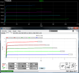
But, I've come across a hitch. I was examining the DC offset of a diamond buffer stage over temperature and found that with some devices, the drift is substantial. I've traced this to a model issue with one device - the KSA1381. I've attached a plot of Vbe vs Temp for three sets of transistors.
MPSA42
MPSA92
KSA1381
KSC3503
MJL1302
MJL3281
The first two sets were simulated at 5mA with the base connected to the collector and the MJL devices were tested at 90 mA.
It doesn't seem reasonable to expect a KSA1381 to not change Vbe very much over 60C of temperature change.
I'm not smart enough on what model parameters may not right or missing for the KSA1381, so I'm hoping that you can point me to where to read about this.
Thanks!
Clarke

I've been using your LTspice models with great results.
But, I've come across a hitch. I was examining the DC offset of a diamond buffer stage over temperature and found that with some devices, the drift is substantial. I've traced this to a model issue with one device - the KSA1381. I've attached a plot of Vbe vs Temp for three sets of transistors.
MPSA42
MPSA92
KSA1381
KSC3503
MJL1302
MJL3281
The first two sets were simulated at 5mA with the base connected to the collector and the MJL devices were tested at 90 mA.
It doesn't seem reasonable to expect a KSA1381 to not change Vbe very much over 60C of temperature change.
I'm not smart enough on what model parameters may not right or missing for the KSA1381, so I'm hoping that you can point me to where to read about this.
Thanks!
Clarke
Are models available for the current production KTA1381 , KTC3503 from KEC ? I suppose we could inquire from Profusion plc , the Europe distributor. On the the bench they test like the obsolete ON parts, except the gains between PNP and NPN are much closer for the KEC parts. They totally blow away the Toshiba parts speedwise in VAS applications.
Thanks for the heads up CG. Vbe temperature dependence is determined by EG and XTI. In all the models where the datasheet includes Ic vs. Vbe plots for different temperatures, I did adjust those parameters to match the plots, but this was not the case for the KSA1381, so I left them as in the model it's based on, which is Bob Cordell's one for the 2SA1381 (note that mine doesn't include XTI but his is 3.0, which is the default value, so it doesn't have to be declared).
I see that the old Sanyo 2SA1381 datasheet does include Ic-Vbe plots at different temperatures, so l'll see if I can match them and update the model. Watch this space...
I see that the old Sanyo 2SA1381 datasheet does include Ic-Vbe plots at different temperatures, so l'll see if I can match them and update the model. Watch this space...
I just looked at the official Sanyo 2SA1381/2SC3503 data sheet, and although the slope of Vbe over temperature looks right, the absolute values for a plot of Vbe over temp at 20mA don't really match. Maybe this is normal?

I changed EG for the KSA1381 to 1.15 and got this. Both at 20 mA.

I changed EG for the KSA1381 to 1.15 and got this. Both at 20 mA.
- Home
- Amplifiers
- Solid State
- LT Spice KSC3503D and KSC1381E lib.