Thanks to PMA remarks I thought of launching a subject on trying to simulate audio amplifiers from a pcb designer perspective.It might have been analysed somewhere else, but I'm not aware of it so let's get started:
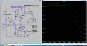
As I'm not really a professional in LTspice simulations , the only tool I know to make a quick check on stability and performance including the pcb design skills is using the cshunt .option. From what I could see, the default settings in Ltspice approximate a .chunt value of 1e-15 which is basically ideal while a true very high quality pcb would be approached by 0.5e-12...1e-13 farrads with a mean average of 1e-12 for sloppy designs and I put togeter a collection of simulations to show the differences that this simple cshunt directive brings into the game. There are simulations done on 2 ohms load, 1khz and 10 khz with 3 values for cshunt and 4 values for the bode plot.Obviously 1pF capacitance between every nodes being the worst nightmare.It can be seen if you bother analysing my printscreens that a 0.5pF difference means around a full order of magnitude in distortions at 10 khz while just about 4...5 times at 1 khz which is kind of predictable . A full picofarad difference can mean a lot more though.
I'd be really thankfull for some other insights like other directives or techniques to simulate the worst case scenarios from a pcb designer perspective and also how to prevent them in the real design.
I myself don't make any pcb design currently and I'm all into solderable pcb breadboard as I can fly wires over any two points avoiding a lot of trouble.I avoid smd components as much as I can and usually i doVERY fine with breadboards that offer lots of me stitching vias to isolate ground loops by design.
Attachments
-
 your usual crappy simulation with no cshunt option.png79.2 KB · Views: 290
 -
 fantastic pcb design.png93.9 KB · Views: 216
 -
 Good pcb design.png26.8 KB · Views: 190
 -
 slightly sloppy pcb design.png27.9 KB · Views: 187
 -
 sloppy pcb 1e-12.png30.3 KB · Views: 171
 -
 V3 NO Cshunt option.png36.6 KB · Views: 185
 -
 Bode 2ohm NO Cshuntoption.png26.7 KB · Views: 159
 -
 Bode 2ohm 1e-14.png20.2 KB · Views: 155
 -
 Bode 2ohm 1e-12.png18.9 KB · Views: 146
 -
 V3 10K 2ohm 1-12.png43.3 KB · Views: 167
 -
 V3 1k 2ohm 1e-12.png45 KB · Views: 173
 -
 V3 10k 8ohm 1e-12.png43.2 KB · Views: 155
 -
 V3 1k 8ohm 1e-12.png40.5 KB · Views: 153
 -
 V3 1K 2ohm 0.5-12.png46.7 KB · Views: 167
 -
 V3 10K 2ohm 0.5-12.png40.5 KB · Views: 141
 -
 V3 1k 8ohm 0.5e-12.png41.1 KB · Views: 179
 -
 V3 10k 8ohm 0.5e-12.png37.3 KB · Views: 140
 -
 V3 1k 8ohm 1e-13.png43.5 KB · Views: 149
 -
 V3 10k 8ohm 1e-13.png41.4 KB · Views: 140
 -
 V3 1k 2ohm 1e-13.png45.6 KB · Views: 222
Last edited:
What do you think about adding estimated inductances of PCB tracks, especially the longer ones and those from bypass capacitors, if they are not directly on PCB layer planes.
It is also possible to add ESL and ESR to any capacitor, in case you have not already done it.
It is also possible to add ESL and ESR to any capacitor, in case you have not already done it.
They probably need to be known in the first place...I obviously have no real power supply here, no decoupling, let alone real world regulator simulations and decopling which are nothing like usual simulations bring in, but if you see what you get by just adding 0.5 pf of capacitance into a simulation can do to these ideal 0.00000x % thd simulations is a lot for me .
From my own experience real world thd on real loads of 0.1% is absolutely fine, basically much better than most speakers ever made as all amplifiers will drive a real speaker in the end.
From my own experience real world thd on real loads of 0.1% is absolutely fine, basically much better than most speakers ever made as all amplifiers will drive a real speaker in the end.
It is a misunderstanding, I was talking about amplifier PCB tracks, their inductances (especially ground tracks) and amplifier capacitors inductances. Do you assume they make no difference? Try to add real inductance of Re output stage emitter resistors and check the influence on stability. No difference? 😉
You need a program that takes the PCB diagram layout, the spice model and then creates an enhanced model with all the capacitances/inductances etc between them.
People have commented that LTSpice isn't superb modelling complex stability for example. However you're also relying on the manufacturers model being relatively correct.
My shunt is current 1e-6.
gmin 1e-12
abstol 1e-12
retool 0.001
chgtol 1e-14
trtol 7
voltol 1e-6
sstol 0.001
mindeltagmin 0.0001
I use the modified trap and normally 'alternate' solver.
@PMA have I implied anything of what your eyes are winking about? By the way I can avoid the inductance of emitter resistors if I want that...I wasn't talking about component's intrinsic parameters here...not even about this schematic which is completely unreal at 4 amps iddle current, but left that way for education purposes.
Attachments

Have you followed this site? I have to admit I have no ideea what a lot of stuff there is about..."Monkey see , monkey does 🙂 "You need a program that takes the PCB diagram layout, the spice model and then creates an enhanced model with all the capacitances/inductances etc between them.
People have commented that LTSpice isn't superb modelling complex stability for example. However you're also relying on the manufacturers model being relatively correct.
My shunt is current 1e-6.
gmin 1e-12
abstol 1e-12
retool 0.001
chgtol 1e-14
trtol 7
voltol 1e-6
sstol 0.001
mindeltagmin 0.0001
I use the modified trap and normally 'alternate' solver.
Last edited:
Have you followed this site? I have to admit I have no ideea what a lot of stuff there is about..."Monkey see , monkey does 🙂 "
At one point I understood the parameters, now.. well there's more to life.
cshunt=1e-6 means 1uF between every node...Are you sure about that?
Yep that's what I thought was set lower :/ and that would be crazy..
1uf between every node and the ground means also between input and ground...I can't imagine the kind of input coupling capacitance you put in your tube headphones amplifiers 🙂
I took this file as my main directive : http://lpvo.fe.uni-lj.si/fileadmin/files/Izobrazevanje/RO/LTspice/Simulator_options.txt
I took this file as my main directive : http://lpvo.fe.uni-lj.si/fileadmin/files/Izobrazevanje/RO/LTspice/Simulator_options.txt
1uf between every node and the ground means also between input and ground...I can't imagine the kind of input coupling capacitance you put in your tube headphones amplifiers 🙂
I took this file as my main directive : http://lpvo.fe.uni-lj.si/fileadmin/files/Izobrazevanje/RO/LTspice/Simulator_options.txt
😛
Perhaps the Mac ltspice resets the values, I distinctly remember running lower previously.
I just tried every of your values except cshunt , also used alternate and every integration method and it's not moving my results even for a bit.
I just tried every of your values except cshunt , also used alternate and every integration method and it's not moving my results even for a bit.
Ahh well. Soldering iron it is 😀

By the way...20nH...1 uH ...https://4hv.org/e107_plugins/forum/forum_viewtopic.php?id=82518It is a misunderstanding, I was talking about amplifier PCB tracks, their inductances (especially ground tracks) and amplifier capacitors inductances. Do you assume they make no difference? Try to add real inductance of Re output stage emitter resistors and check the influence on stability. No difference? 😉
cshunt specifies the capacitance from every node to ground, not between every node. When I read this thread, I became confused and just like to clarify thatcshunt=1e-6 means 1uF between every node...Are you sure about that?
While building my latest amplifier, I encountered stability and oscillation in reality that did not show in simulation. Once I added a lot of tiny inductors in series with each component terminal, the simulation became more realistic and I was able to approximate what I was observing on the bench.
The cshunt option is helpful, but considering the inductance is at least equally important.
In case the PCB design is done already, one can put actual connections and their estimated inductance values into the simulation. In case the PCB design is not done, 10nH may be a good starting point and this is more realistic than no inductance at all.
I found that the number of components for approximating the PCB may outnumber the actual components by far. Sure, this is a lot of additional complexity, but may be worth it.
Inaccurate component models are another story.
With gaining more experience, I wouldn’t overestimate the result of simulation. It is good for checking the concept, but likely the numbers derived don’t mean too much actually.
If you consider the [pF]-capacitances of components pads and traces you also have to consider trace- and other inductances.
Capacitances are often tiny (not saying they should be neglected) but you quickly have 100´s of [nH] or more in typical audio amplifiers you see around here.
Especially critical in feedback paths, more so than in emitter resistors.
Just plug typical numbers of traces in an inductance calculator.
There is little use to low inductance and expensive emitter resistors when you effectively create a feedback path with a tank circuit and make your amplifier oscillate/unstable anyway.
See figure 3a+b here for a more complete simulation:
A Practical Guide to High-Speed Printed-Circuit-Board Layout
And even figure 3b ignores parasitics.
There is more inductance in each component wire, the resistors themselves (although in this example they probably assume tiny SMD resistors as it is about RF circuitry), etc...
Look at this for example:
Wayne's Burning Amp 2018 Linestage
Each transistor probably has at least 5nH in each of its legs. Small compared to the trace inductances but it all (can) add(s) up.
Last edited:
I tried following the link's recommendations for inductances, modified the circuit for optimal class AB operation, added most of the necessary series resistances and in the end the Cshunt directive is still the true king. Simulating the speaker itself would be a much bigger problem for me, but at least from a pcb perspective this I think is a good approach of the problem even if it doesn't show the full picture as you need to properly compensate for the first 100khz...1 Mhz bandwidth in the first place.Now this simulation shows DC instability for some reason, but that's just a different discussion. I'm actually building this amp I hope in a little bit different version adding some germanium trz in the mix although i might end up using this one as is now.I considered first using a balanced version but that doesn't allowme any germanium trz in the mix and I'm a great believer in the Quad/QSC virtual ground output coupling the speaker through capacitors soI'll probably sacrifice the good watts for some lcr natural damping of the woofer.While building my latest amplifier, I encountered stability and oscillation in reality that did not show in simulation. Once I added a lot of tiny inductors in series with each component terminal, the simulation became more realistic and I was able to approximate what I was observing on the bench.
The cshunt option is helpful, but considering the inductance is at least equally important.
In case the PCB design is done already, one can put actual connections and their estimated inductance values into the simulation. In case the PCB design is not done, 10nH may be a good starting point and this is more realistic than no inductance at all.
I found that the number of components for approximating the PCB may outnumber the actual components by far. Sure, this is a lot of additional complexity, but may be worth it.
Inaccurate component models are another story.
With gaining more experience, I wouldn’t overestimate the result of simulation. It is good for checking the concept, but likely the numbers derived don’t mean too much actually.
Have some fun yourself if you feel like.
Attachments
-
 V4 realistic thd.png48.3 KB · Views: 82
 -
 V4 realistic Bode.png36.2 KB · Views: 83
 -
 V4 not that good thd.png44.7 KB · Views: 72
 -
 V4 not that good Bode.png36 KB · Views: 72
 -
 V4 good thd.png45.6 KB · Views: 77
 -
 V4 good Bode.png35.3 KB · Views: 75
 -
 V4goodstepresponce.png39.2 KB · Views: 82
 -
 V4 realistic step response.png34.4 KB · Views: 74
 -
kl01AA.asc12.4 KB · Views: 59
-
 20220528_141352.jpg523.6 KB · Views: 82
Last edited:
Thanks for the document, that's a good one.My first and only try to pcb work was a 6 weeks work while I learned Altium a few years ago , but nobody paid me doing that sh*t so I reverted back to my prototyping boards with flying wires...Although I have very good books on that I'm not really passionate about pcb design to be honest: https://www.diyaudio.com/community/threads/modified-aiwa-riaa-j-fet-phono-preamp.328172/post-5572084If you consider the [pF]-capacitances of components pads and traces you also have to consider trace- and other inductances.
Capacitances are often tiny (not saying they should be neglected) but you quickly have 100´s of [nH] or more in typical audio amplifiers you see around here.
Especially critical in feedback paths, more so than in emitter resistors.
Just plug typical numbers of traces in an inductance calculator.
There is little use to low inductance and expensive emitter resistors when you effectively create a feedback path with a tank circuit and make your amplifier oscillate/unstable anyway.
See figure 3a+b here for a more complete simulation:
A Practical Guide to High-Speed Printed-Circuit-Board Layout
And even figure 3b ignores parasitics.
There is more inductance in each component wire, the resistors themselves (although in this example they probably assume tiny SMD resistors as it is about RF circuitry), etc...
Look at this for example:
Wayne's Burning Amp 2018 Linestage
Each transistor probably has at least 5nH in each of its legs. Small compared to the trace inductances but it all (can) add(s) up.
Besides I'm not sure how they transfered the Dolby SR on pcb either...but having tons of 1V/us LF442 doing all the job there working at a few tenths to hundreds of milivolts levels( with35nV/sqr rootHz of noise, yes good engineers can work with that in the milivolts range !) is probably the key to a succesful transfer that modeled the world of tape recordings.When I see people advancing op-amps working at 50...3200v/us claiming to be the only ones capable of rendering a stereo image that was litterally produced on 1v/us op amps dealing with tapeheads histeresis kind of slew rates I can only think of pure incompetence within electronics domain... I had a lengthy article on linkedin about why I consider Dolby the real god of audio electronics, but I'm not going back to that again, I just see a full void that every audiophile avoid ...
Attachments


- Home
- Design & Build
- Software Tools
- Ltspice "armchair design" and insides into sloppy PCB design