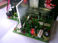
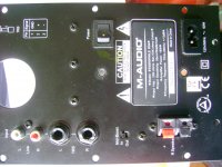
DX4 Speaker No sound Looks dead [/B]
I have a problem with my DX4 speaker system.No sound and no lite up.Nothing. totally dead.
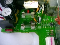
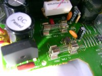
I checked the fuses . both of them are good
RS404 bridge rectifier out put is 48.2DC volts. Is it ok.
TDA 2030 IC also looks good. Not removed yet. Is 48.2v input ok for this IC.
What is the possible case?
I love this this spks sound as it is too nice .
Pl provide some technical advice.
Thank you and very appreciate your help.
No 48V is not ok. TDA2030 max is +-18V (36V).
Is it possible this set was built for a country with lower AC mains voltage than your location uses?
Start with something simple, trace the circuit to the light(ing), see if power is getting to it. I do not know the details of this amp's construction, it could be helpful if you provided a good top-down picture of the entire internal PCBs.
DX4 No sound
Thanks for your help.
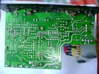
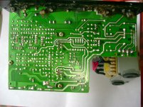
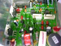
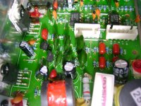
Here you find some Pics and some information.
Voltage regulator WS 78L12
OP amp IC 4558D JRC
TDA 2030
Bridge rectifier RS 404
Some voltage values🙁Refer the pictures for ABC...)
between A&B 36V~
between A&E 18V~
between C&E ,C&B , C&A , E&D , 24 V
between C&D 48 V
both Fusees were good
When power on TDA 2030 heat sink gets normal hot.
power on indicator LED gone
Where is the power indicator LED? Try to trace back that circuit so we can see how the power gets to it. Does the power LED connect to the small white plastic connector labeled "CN3A"?
If so, measure for DC voltage at the pins on CN3A.
Also, measure for DC voltage at the +- power pins of both TDA2030, and both JRC4558. It looks as though the 36VAC input from the transformer is too high, that there may be something wrong with the transformer, assuming you have 110VAC to 120VAC from the wall outlet then I would wonder about a short in the transformer's primary windings, and yet, there should have been a thermal fuse that tripped if it got too hot.
I then wonder, if the rectified 48V DC was too high for the power indicator LED and damaged it. If you measure more than 2VDC on the CN3A pins, I would suspect it is a damaged LED, but that the amp does not work otherwise because excessive voltage damaged either the TDA2030, the regulators for the opamps, or the JRC4558 opamps themselves.
Last edited:
Does the power LED connect to the small white plastic connector labeled "CN3A"?
YES
DC voltage at the pins on CN3A = 0.7VDC
I think transformer is operating ok.
please see the pic.
There are 2 voltage regulates. 78L12. At the near to the fuses. ( R )
voltages across the pins I have noted on the diagram.
out put of one of the voltage regulator is only 0.7VDC . Should it be 12VDC?
TDA2030 ICS : Across +Vs and -Vs pins 48VDC
RS404 bridge Rectifier :Across the + & - pins 48VDC.
JRS 4558D IC : Still I am trying to find out + & - pins.
Yes The transformer has thermal fuse that tripped if it got too hot.
YES LED damaged already.
The heat sink fixed to the TDA 2030 is getting hot when Amp power switch on.
Picture shows:
A B out put from the transformer.
C- & D+ out put from RS404 bridge rectifier Across CD 48VDC
R1 R2 Voltage regulator 78L12 R2 out put only 0.7 VDC
F1 F2 TDA 2030
H and H the JRC4558.
Thank for your help
IF you need more details i am ready .
Thanks again
Attachments
TDA2030 cannot operate at 48VDC, look at its spec sheet, page 2, "Absolute Maximum Supply Voltage" - +-18V (36V).
http://www.st.com/internet/com/TECHNICAL_RESOURCES/TECHNICAL_LITERATURE/DATASHEET/CD00000128.pdf
It is not likely they would have built this with a 36VAC transformer, which would correctly output the 48VDC you measured. I must conclude that one of three things is true:
A) While the speaker is for a market with 120VAC mains power, your mains power is higher than 120VAC.
-OR-
B) The transformer is shorting out or modified so it is no longer outputting the correct voltage.
-OR-
C) It is not the original transformer, someone replaced the original transformer with one having too high a voltage rating and it has caused damage.
What is the history of this speaker? Did it work previously while in your possession? Has it had any repairs done?
It does indicate a problem with the 78L12 regulator that it is only outputting 0.7V. I mean that I assume you have the orientation of the 2nd 78L12 reversed because it does not seem possible it could input 0.7V and output 24V, so I assume it is inputting 24V and outputting 0.7V - unless someone has replaced it previously and has soldered it in backwards, OR if this was a manufacturing defect and the speaker had never worked when new.
"Hopefully" the regulators 78L12 for the opamps, have kept them from being damaged, hopefully only one 78L12 regulator needs to be replaced, but I suspect that both of the TDA2030 need to be replaced due to overvoltage damage.
Here is what I propose (the order in which to repair):
1) Get a different transformer. Since TDA is rated for +-18V maximum, the transformer should be rated no higher than 13-0-13 VAC (+-13V dual winding or center tapped).
2) Replace the 78L12 reading 0.7V. Before soldering it in, measure voltage at that spot on the PCB to be sure the input voltage is higher than the ground voltage, to be sure the orientation of the regulator is correct and not reversed.
3) Test the speaker. If no audio from each or either channel, you may need to replace the TDA2030 chips. The one you have labeled as F2, it looks like the solder is melted or poorly done, what happened to that? It also looks like a trace is broken where it would pass between pin 1 and 3, which seems strange, follow that trace and figure out where it is supposed to go.
Last edited:
Thanks Thanks thanks.
Thanks
So I already ordered 78L12 voltage regulators and got some idea about my amp from your comments.
Thanks again.
I will let you know the updates soon.
thanks agin
Thanks
So I already ordered 78L12 voltage regulators and got some idea about my amp from your comments.
Thanks again.
I will let you know the updates soon.
thanks agin
Looking again at the picture, I don't think there is a broken trace that ran between pin 1 and 3 on the TDA2030, but inspect the traces going to all the pins on TDA2030 because I can't tell if all are ok or shorting out, or how the soldering is on those pins.
If that TDA2030 is damaged and needs replaced, which wouldn't be surprising since it looks as though it got so hot that it damaged the traces and melted the solder joints, you may end up having to repair the traces or air-wire from the traces to the next component in the circuit.
If that TDA2030 is damaged and needs replaced, which wouldn't be surprising since it looks as though it got so hot that it damaged the traces and melted the solder joints, you may end up having to repair the traces or air-wire from the traces to the next component in the circuit.
M-Audio TDA2030
Hi, Can you tell me the other channel audio amp in this pic with the TDA2030?
I have this speaker set but someone put audio into the speaker output and blew out the amp.
Hi, Can you tell me the other channel audio amp in this pic with the TDA2030?
I have this speaker set but someone put audio into the speaker output and blew out the amp.
I need IC 4558D circuit diagram for subwoofer
I need IC 4558D circuit diagram. for subwoofer
please help me frnds
I need IC 4558D circuit diagram. for subwoofer
please help me frnds
- Status
- Not open for further replies.
- Home
- Amplifiers
- Chip Amps
- M Audio DX 4 No sound Looks dead
