Is it possible to measure the AC component of a DC power supply using just a Fluke 87V?
My theory is, you can do this by measuring DC, using the REL button, then switching the meter to measure AC.
I have zero relevant experience and am willing to buy a scope if necessary but right now I just need to know if I am fooling myself with the numbers I am seeing.
Thanks!
My theory is, you can do this by measuring DC, using the REL button, then switching the meter to measure AC.
I have zero relevant experience and am willing to buy a scope if necessary but right now I just need to know if I am fooling myself with the numbers I am seeing.
Thanks!
All things are possible (mostly 🙂) but not always practical. You could just AC couple the PSU output through a cap to block the DC and then with a high value load resistor measure the 'AC component'.
Trouble is, the AC might be quite small, and it will also definitely be irregular in shape (sawtooth typically) and so whatever your meter measures may bear no resemblance to actual voltage levels present.
Trouble is, the AC might be quite small, and it will also definitely be irregular in shape (sawtooth typically) and so whatever your meter measures may bear no resemblance to actual voltage levels present.
On Fluke meters that have a AC mV readout it works by averaging the AC component (input is already AC coupled) and it is an approximation, useful only for comparing other (relative) measurements made on the same meter but not for absolute values.
I do find it useful to measure output noise levels but it's just easier to hook it up to a soundcard and look at the FFT.
I do find it useful to measure output noise levels but it's just easier to hook it up to a soundcard and look at the FFT.
Is it possible to measure the AC component of a DC power supply using just a Fluke 87V?
My theory is, you can do this by measuring DC, using the REL button, then switching the meter to measure AC.
I have zero relevant experience and am willing to buy a scope if necessary but right now I just need to know if I am fooling myself with the numbers I am seeing.
I don't know why you would need to measure the DC output of a power supply in order to know its AC output.
Why just not measure the power supply's AC output?
The obvious difference between using a Scope and a DVM is the bandwidth of the measurement. For example my better TRMS DVM's have about 100 KHz bandwidth, and my 20 mHz scope seems to have about 20 mHz bandwidth, which can result in very different readings with some signals.
A typical ripple waveform has few components beyond 1~2KHz, thus the bandwidth of an ordinary multimeter is quite sufficient (not for a SMPS!).
For a typical ripple sawtooth, the peak-to-peak to rms ratio is ~3. You don't need much more absolute accuracy than that for this type of measurement.
For a typical ripple sawtooth, the peak-to-peak to rms ratio is ~3. You don't need much more absolute accuracy than that for this type of measurement.
I am building a kit and the instructions say to check the AC component to ensure the regulator is doing its thing. I was hoping the Fluke 87V would be able to measure the ripple as it is a "true RMS" meter, and the numbers I see are within the specifications in the kit. (1-2 mV on a 300V DC output). They bounce around a bit and then settle down, but maybe I'm just fooling myself and the meter is just reporting its own noise or something.
The 87v is a good meter. Just put it on AC and make the measurement. FWIW, I'd expect a decent regulator circuit to have very little ripple, and the meter should just read near it's residual/offset/zero, similar to what it reads with the leads shorted together. I'd measure the ripple both before and after the regulator just to prove to myself that I was doing the measurement right, and the regulator was regulating. BTW, convention is that if an AC measurement is unspecified, it's RMS. If they want peak or peak-to-peak, it should say so.
Last edited:
Thank you all for your assistance! I am having lots of fun and who knows, when it's done I might post some pictures.
Fluke makes a good meter, I have used mine for decades, and measuring ripple on DC with it is something I do all the time. SOme cheaper meters are fooled by DC when on AC readings. There is a very simple test. Set your meter to AC volts, then measure a 9v battery. If the reading settles to zero volts in a second or two, then your meter will read AC on DC. If the meter cannot do this, your AC scale will read substantial DC, and be useless for this.
A fair quality digital multimeter should isolate AC component and should measure it, even you have a large DC voltage. If the meter does not de the job and give you a bad reading you can use a capacitor to get rid of the DC voltage ( same old trick as input coupling on an oscilloscope )
Attachments
Another option is to use something like audacity, and your pc's soundcard to record your power supply rails (with suitable DC blocking cap, and possibly some resistance).
You then look at the fft of the recorded wave form and you will see the ripple and it's harmonics 🙂
I first saw the idea here http://www.diyaudio.com/forums/power-supplies/184068-psu-rc-multistage-filtering.html and have done it myself 🙂
Tony.
You then look at the fft of the recorded wave form and you will see the ripple and it's harmonics 🙂
I first saw the idea here http://www.diyaudio.com/forums/power-supplies/184068-psu-rc-multistage-filtering.html and have done it myself 🙂
Tony.
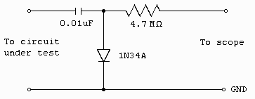
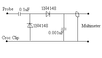
If you were measuring ripple at the main filter caps in a large amp power supply, which means quite a few volts (easily 4 or 5V) , then you should build a peak or peak to peak probe, aand use your multimeter to read the resulting DC:
Old timers used it to measure RF voltages, at frequencies way beyond what their meters could handle, so they called them "RF probes".
You build the same, without the 4M7 scaling resistor, and you'll get peak ripple voltage

or the peak to peak version:

replace the .001uF cap with a 0.1uF one, you are not worried about loading the circuit you are measuring 😉
That said, doubt these can measure 1 or 2mV ripple, but these are very useful tools to check high power amplifier supplies.
Old timers used it to measure RF voltages, at frequencies way beyond what their meters could handle, so they called them "RF probes".
You build the same, without the 4M7 scaling resistor, and you'll get peak ripple voltage

or the peak to peak version:

replace the .001uF cap with a 0.1uF one, you are not worried about loading the circuit you are measuring 😉
That said, doubt these can measure 1 or 2mV ripple, but these are very useful tools to check high power amplifier supplies.
- Status
- Not open for further replies.
- Home
- Design & Build
- Equipment & Tools
- Measuring ripple without a scope
