Hey All,
This is my first post here, so please be gentle.
I've got a bit of an issue on my hands. I picked up a Melody SP3 (not an ONIX SP3) a couple years back as my first foray into tube audio, and I've been really pleased with the thing. I picked up a pair of Onix Reference 1's and a Jolida JD9 to go with it and it sounds fantastic.
Well, one of my power tubes is now on the fritz, and I can't seem to find any info on my actual amp to move toward replacing tubes and biasing. My particular amp is different than the Onix SP3 I've so often seen pictures of - it has a separate power button on the left, and a smaller flat-style volume knob on the right. It also only has one set of RCA inputs on the back. I've attached picturea of the unit to this thread.
The literature included with my amp looks like it's a photocopied version of the literature for the Onix amp, and I'm not sure if the electrical specs are the same. I can tell you that the power tubes for the unit I have are 6P13P's. I've looked all over online for biasing instructions and all I've been able to find links to are instructions for the Onix SP3 on the AV123 forums, which are dead and have been for a while.
I'm hoping someone has something archived or lying around that they can provide me, or perhaps someone can chime in with some helpful information. I may try replacing the power tubes with the same model and hope I can get by without biasing for now, but I'd really like to learn more about my tube amp if possible, so whatever documentation or information anyone can provide would be helpful. I can also take pictures or answer questions as needed. Thanks in advance, everyone, and happy holidays!
- Dan
Attachments
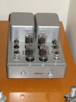


I thought the output valves looked familiar, they are EL36 or 6L6GC.
https://www.google.co.uk/search?q=m...ei=amZYWImyFY_gUsO3odgP#imgrc=aRuEA2zKsFQwhM:
https://www.google.co.uk/search?q=m...ei=amZYWImyFY_gUsO3odgP#imgrc=aRuEA2zKsFQwhM:
To clarify, the photos I posted were found online. They are not photos of my actual unit. I'll post those in a couple of hours once I'm home.
I believe your particular version uses 6L6ish outputs so 6P3SE would be a good replacement.
It seems to have cathode followers DC coupled to the output grids.
Does it have one or two bias adjustment trimmers?
Can you post pictures of the inside? Please be careful and make sure it has been switched off and disconnected for some time.
How confident are you with working around dangerous voltages? I ask as you may need to take a few measurements so we can help you.
OK, just saw your last post so maybe it is El36 or 6L6oid?
Cheers
Matt
Last edited:
Hey Guys,
Thanks for the responses so far! I got home and took a few pictures, which are attached. I can't, for the life of me, locate any biasing pots, so any help in that regard would be awesome.
Also, I numbered the tubes in one picture. The numbers correspond to tube models as follows:
1 - 2x 6N3-J
2 - 2x 6N1-Q
3 - 2x 12AX7 / ECC83 (Melody branded)
4 - 4x 6P13P
As far as working around the voltages, I think I can handle it. I did take measurements on the two left power tubes and they read ~300v at the moment, so I am going to have to discharge this before I do any deeper digging, I believe.
Thanks again for all the help!
- Dan
Attachments


Interesting, it does use 6P13P.
Looking about they don't seem to have a direct equivalent. The Russian 6P36S uses quite a bit more heater current and has a different pin out. The EL36 is ok on heater current but different pin out again.
I think you will have to source some 6P13P from China or rewire the sockets to use EL36/6CM5.
Also as there is only the one bias pot per channel they will need to be matched.
Sorry I couldn't be more help. It is quite an obscure amp. Hopefully someone else will chime in with a better plan.
Cheers
Matt
Thanks Matt!
So now I suppose I have to make a choice on whether to find some 6P13P's (which look obtainable via eBay) or re-wire. Being the power tubes, do you think there's much advantage to re-wiring vs finding direct replacements? I'm not familiar enough with all of this to know how much work would go into re-wiring vs. how much I would stand to gain from the different power tubes.
Being that I have only two bias pots, would that more likely mean that each pot controls one preamp, one phase inverter, one driver, and two power tubes (i.e. one pot for the entire left side of the amp and one pot for the right) or would the power tubes be hard set and therefore not need biasing? Also, would I (theoretically) not need to bias the power tubes if I replaced them with additional 6P13Ps?
If I end up messing with biasing, I will need to figure out the bias voltage by taking readings with my multimeter (I understand this can be done with the plate voltage, the cathode voltage, and the cathode resistance). This might prove to be a good crash course in learning more about tube amps work. However, if I won't likely gain much from swapping the power tubes and I can avoid re-biasing altogether, that might be my preferred route, at least until I can figure out what I want to do with swapping out the smaller tubes.
Thanks again!
Dan
As I don't read hanji, the 6P13P data sheet is of limited utility. Still, substantial heater power seems available. The O/P transformers look pretty hefty. Some sort of conversion to an easily sourced O/P tube should be doable, after the safety issue is addressed.
Unless the builders did what Fisher did (true fixed bias), self (cathode) biased "finals" are present. Nothing gets adjusted.
I can't, for the life of me, locate any biasing pots, so any help in that regard would be awesome.
Unless the builders did what Fisher did (true fixed bias), self (cathode) biased "finals" are present. Nothing gets adjusted.
There is two pots sitting in beds of white silicone on the circuit board. Look for the blue rectangular things with the brass screws.
Bias adjustment is just for the output tubes.
BillWojo
Bias adjustment is just for the output tubes.
BillWojo
I don't see a power transformer. 😡 Are we dealing with a death trap?
Could it be housed inside one of the giant metal boxes sticking out the top of the unit? The exposed board photo is taken from the bottom, but those two metal housings on the top are the only place I could think of that it would be.
There is two pots sitting in beds of white silicone on the circuit board. Look for the blue rectangular things with the brass screws.
Bias adjustment is just for the output tubes.
BillWojo
Bill,
So that's what biasing pots look like! Haha, thanks for pointing them out. I would have been searching forever.
- Dan
I found these guys on eBay that I think will drop right in, from what I've read on other threads:
4x 6P13S / EL36 / 6GC6 / 6P31S BEAM TETRODE !!!NEW!!! | eBay
I may do that for now, as I've never re-wired anything in my life, and I fear I have a lot of learning to do before I start messing with that stuff. Still, I do plan to take some measurements so I know all of my specs and I can re-wire in the (semi-near) future. I just have no idea where to even start looking for how to re-wire an amp for different tubes, especially with no original literature for the thing.
- Dan
From the link in that John posted back at the start the bias pots are for the grids of DC coupled cathode followers before the outputs. One per channel.
I too don't see a power transformer either Eli. Maybe one can holds a power transformer and the other the output transformers?
Seems odd to run pentode outputs with cathode followers driving em with such small output transformers. That is if they are in one can.
Also this could be a problem with the GNFB as changing output valves may change the gain. If the OPT are small this may or may not be a problem.
Cheers
Matt
OK, looking at the pictures again. This is not a "death trap" even though Eli was quite right to point that out. Could have been a bin job there my friend.
Clearly there is a power transformer in one can and possibly even a choke? Take a look if you can.
I am pretty certain on this as the heaters don't add up for death trap service. Plus all the speaker output wiring comes from one can.
Cheers
Matt
Clearly there is a power transformer in one can and possibly even a choke? Take a look if you can.
I am pretty certain on this as the heaters don't add up for death trap service. Plus all the speaker output wiring comes from one can.
Cheers
Matt
Whew on safety not being an issue.
Somebody with hanji expertise needs to comment. However, my limited reading of the Chinese data sheet suggests that the 6CM5 would be OK.
BB, rewiring the O/P tubes is pretty easy. 😉 If you look at the 2 data sheets previously linked, you will see that more than 1 wire remains untouched. The pinout diagrams count clockwise, viewed from underneath.
I think that the pots you see may not be for output biasing, but for phase-splitter balance.
It looks like there is cathode biasing on the output tubes (470 ohm resistors at centre of PCB), and bypass electrolytics nearby.
However, I may be wrong, as I have worked on other Melody amps that bias via direct coupled driver tubes. Still unusual to only have one pot per pair of tubes. Really need to trace where the cathodes of the final tubes go.
The 6P13P is a nearly exact equivalent of the EL36, 6CM5 tubes. Russian version is 6P13S.
- Status
- Not open for further replies.
- Home
- Amplifiers
- Tubes / Valves
- Melody SP3 Tube Replacement and Bias Assistance