Does anyone have a schematic or manual for this unit? Previous owner removed parts from board and played with the wiring. I've already checked all of the usual places; can't find a thing. It seems to be a pretty rare piece. ANY help would be greatly appreciated.
Hi,
My first ever valve preamp.😎
The only thing you can find on the internet is a hand drawing of the phono section, no PSU.
http://www.google.be/url?sa=t&rct=j&q=&esrc=s&source=web&cd=3&cad=rja&uact=8&ved=0CDUQFjAC&url=http%3A%2F%2Fwww.cieri.net%2FDocumenti%2FSchemi%2FMichaelson%2520%26%2520Austin%2520-%2520Preamplificatore%2520TVP-1.pdf&ei=f9UOVJXVCKXN7AbZ4IFo&usg=AFQjCNFH9q8hwZCtVbyNi_ybc4M_qAJfXQ&bvm=bv.74649129,d.bGQ\
Ciao, 😉
TVA-1 information and schematic
Hi audio king,
I have gathered a lot of information from some hi-fi interested people concerning repair and wiring of the Michaelson & Austin , TVA-1 valveamp. 🙂.....but not the TVP-1😱
I shall try to ask about the TVP-1 preamp schematic in UK.
To share the experience with others about amplifiers and speakers, I made a setup on the amateur site called: TUBEAMP .
Unfortunately the company closes their activity , and I have tried to make a copy of the Tubeamp site on Google Sites:
https://sites.google.com/site/httpstubeamp/
The site is under construction, but you will be able to find some answers and links to my Picasa Web about "Tim's Valveamp number 1" , TVA-1.
Tim De Paravicini designed the amplifier for M&A, and I have recently received ground wiring information from a friend in UK.
I assume that TDP made the TVP-1 as well.
I hobe that Google Sites stays with this website possibility... .....🙂
Kim
Anybody? Pretty please..........😕
Hi audio king,
I have gathered a lot of information from some hi-fi interested people concerning repair and wiring of the Michaelson & Austin , TVA-1 valveamp. 🙂.....but not the TVP-1😱
I shall try to ask about the TVP-1 preamp schematic in UK.
To share the experience with others about amplifiers and speakers, I made a setup on the amateur site called: TUBEAMP .
Unfortunately the company closes their activity , and I have tried to make a copy of the Tubeamp site on Google Sites:
https://sites.google.com/site/httpstubeamp/
The site is under construction, but you will be able to find some answers and links to my Picasa Web about "Tim's Valveamp number 1" , TVA-1.
Tim De Paravicini designed the amplifier for M&A, and I have recently received ground wiring information from a friend in UK.
I assume that TDP made the TVP-1 as well.
I hobe that Google Sites stays with this website possibility... .....🙂
Kim
Last edited:
Anybody? Pretty please..........😕
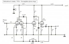
Received this circuit from UK, which could be the phono stage from TVP-1 ?:
Attachments
Last edited:
I'm pretty sure the connection shown to the grid of the right hand section of the ECC83/12AX7A is a mistake, it should be wired in parallel with the grid on the input side.
Interesting how the HF feedback is taken before the cathode follower with just the extreme LF taken from the output. This would tend to prevent external capacitive loads from affecting the accuracy of the RIAA equalization.
Note most cap values are shown in nF which might be less than obvious at first pass.
The schematic in the previous post seems to be a redraw of the schematic Frank found on google.be.
Something else to note is that the cathode follower section of the second ECC83 is running at 3mA which is pretty high for this type. Seems like a 12DW7 if pinned out correctly might be a better choice in this position.
I have found an identical hand-drawn schematic on the web. In that drawing,there is a question mark on the line from the grid of the second triode section and the output of the 100n cap. I'll have to look at the board to verify this.
Hi,
That's the one I linked to in post #2.
From memory, I had drawn the complete diagram but lost it somehow, Kevin's analysis is correct.
The line stage uses a pair of ECC82s where one triode section is configured as a current source.
A topology TDP used throughout for the flagship TVP-X.
I used this preamp with Quad ESL 57s and found it to be quite nice sounding although a bit bass shy compared to my second pre a Counterpoint SA5.
The TVP-1 is not an easy unit to restore though with all the coax harnesses and such. My unit had been tampered with as well.
Best, 😉
I have found an identical hand-drawn schematic on the web. In that drawing,there is a question mark on the line from the grid of the second triode section and the output of the 100n cap. I'll have to look at the board to verify this.
My friend from UK also found the mistake with connection from grid nr. 2 to the capacitor..... should have been to grid nr. 1
It seems that you have sufficient help with your preamp now....................
Does anyone have a schematic or manual for this unit? Previous owner removed parts from board and played with the wiring. I've already checked all of the usual places; can't find a thing. It seems to be a pretty rare piece. ANY help would be greatly appreciated.
I have asked Papworth Audio Technology about the TVP-1 schematic, and I was told, that they never received the schematic, when they purchased the company...the company that actually made the TVP-1.
A guy in US owns the TVP-1 and he intends to make a drawing from the preamp. This work may take a while, so I could suggest as follows:
You could take a close up picture of your preamp PCB from the component side ( may be two pictures if the PCB is a A4 size), and after that one or two pictures from the soldering side, and post the pictures . Then we might have a chance to make the schematic.
Overall, it's limited how many ways valves in a preamp can be connected.
Some people has erlier tried to ask T.d.P., but the general guess was, that T.d.P would not make the circuit available.
I have trouble believing that Tim would have designed that circuit. He's quite skilled and accomplished.
I have trouble believing that Tim would have designed that circuit. He's quite skilled and accomplished.
If you have the circuit, could you please share it with us?
Is that a guess, or do you have knowledge from the source?
Tim's Valve Preamp no. 1.... hence TVP-1.
This is just a retelling of the info received from the company which bought Mentmore Industries. Mentmore took over as M & A closed down.
I don't have the circuit (and if I did, I would be hesitant to share confidential information), but I've spent time with Tim, know his work well, and know enough about tube circuits to see lots of things wrong with this that Tim would be unlikely to do.
I don't have the circuit (and if I did, I would be hesitant to share confidential information), but I've spent time with Tim, know his work well, and know enough about tube circuits to see lots of things wrong with this that Tim would be unlikely to do.
Let's stick to the facts.
Circuits owned by others should not published, but after a certain period any patents runs out, as it were with Mr. D. Hafler's "ultra-linear" design. Mr. Haflers patent expired ...was it after 25years?
Mentmore bought M & A after they went broke back in the early nineteen eighties, and since we're talking about a circuit which is over 30 years old, it's difficult to imagine that copyright is being violated.
It would have been a great help with a couple of circuit lines from you, especially when you know him and his topology that well.
Patents have nothing to do with it- that's public information by definition. Trade secrets are owned by their owners, copyrights on drawings last a long, long time, and you may want to reread the first few words of my post. 😀
There are fundamental problems with the circuit you posted. Tim is smart and does not design circuits with fundamental problems. Draw the obvious conclusion.
There are fundamental problems with the circuit you posted. Tim is smart and does not design circuits with fundamental problems. Draw the obvious conclusion.
GIYF. If you go on the EAR website and read Tim's bio, he only did the TVA-10 and M-200.
..:: EAR Yoshino, professional audio equipment,Cambridgeshire,UK ::..
he also says a little about M&A in Tim de Paravicini Page 2 | Stereophile.com
The presented hand drawn diagram does not seem to be a TdP design.
I like Tim, he has the most awesome beard in the UK hi-end since LJK Setright died.
..:: EAR Yoshino, professional audio equipment,Cambridgeshire,UK ::..
he also says a little about M&A in Tim de Paravicini Page 2 | Stereophile.com
The presented hand drawn diagram does not seem to be a TdP design.
I like Tim, he has the most awesome beard in the UK hi-end since LJK Setright died.
Patents have nothing to do with it- that's public information by definition. Trade secrets are owned by their owners, copyrights on drawings last a long, long time, and you may want to reread the first few words of my post. 😀
There are fundamental problems with the circuit you posted. Tim is smart and does not design circuits with fundamental problems. Draw the obvious conclusion.
It's difficult to see any business secrets regarding any preamplifiers more than thirty years old. The development is a long time ago over and done in respect to this preamp.
The indefinable time you write about copyright may stand for itself.
This is a waste of time. The Intention was good. End
Hi,
Wasn't Mentmore Industries the manufacturing arm of M&A?
Anyway, I too remember the TVP-1 as being designed for them by TdP who then worked as a consultant.
This was mentioned in the leaflets you'd pick up at hi-fi shows in the U.K.
That said, it wouldn't surprise me at all if the circuit diagram as shown here in previous posts is incomplete or even contains more errors.
Cheers, 😉
This is just a retelling of the info received from the company which bought Mentmore Industries. Mentmore took over as M & A closed down.
Wasn't Mentmore Industries the manufacturing arm of M&A?
Anyway, I too remember the TVP-1 as being designed for them by TdP who then worked as a consultant.
This was mentioned in the leaflets you'd pick up at hi-fi shows in the U.K.
That said, it wouldn't surprise me at all if the circuit diagram as shown here in previous posts is incomplete or even contains more errors.
Cheers, 😉
GIYF. If you go on the EAR website and read Tim's bio, he only did the TVA-10 and M-200.
..:: EAR Yoshino, professional audio equipment,Cambridgeshire,UK ::..
he also says a little about M&A in Tim de Paravicini Page 2 | Stereophile.com
The presented hand drawn diagram does not seem to be a TdP design.
I like Tim, he has the most awesome beard in the UK hi-end since LJK Setright died.
He might have a nice beard , mr. Tim d.P. , but let's stick to the historical facts:
https://sites.google.com/site/httpstubeamp/
- Home
- Source & Line
- Analogue Source
- Michaelson&Austin TVP-1