Hi all. I'm new to this group, but it seems full of very knowledgeable people and I wonder if you'd be able to help me out? I have a pair of mission 770 freedom Mark V which I really do love. I keep on comparing them against other speakers and they keep on coming out better however looking at the crossover I see that one of the resistors has got so hot that it's melted the plastic that has attached to so I think there must be some serious need for replacing some of the components such as the resistors and capacitors. Of course these are 40 yrs old and I'm a rank amateur in recognising and decoding the codes on the components so that I can replace them. Anyone to hold my hand through this would be much appreciated. Note I have looked at other posts and there is nothing that answers my questions. .
Many thanks
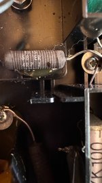
- Do Resistors generally need replacing? Should they get so hot? code ERG 5.8 ER 4R7J -all i can see. I was advised there are differing values present
- There is one bipolar cap - code 93-8730 . What is the replacement value?
- There is one film cap 4u 7K100 Apparently these do not need replacing?
Many thanks
Attachments


1 - measure the value and see if it's within tolerance
2 - that looks like the date code, not the value
3 - metallized film caps will last indefinitely unless they are severely over driven with current
old bipolar capacitors often need to be replaced
but you really need a schematic
2 - that looks like the date code, not the value
3 - metallized film caps will last indefinitely unless they are severely over driven with current
old bipolar capacitors often need to be replaced
but you really need a schematic
There appears to be a history of overheating with this particular model.
1 - Replace each resistor with a wirewound resistor of higher power rating - say 20 W.
2 - Remove the blue bipolar electrolytic capacitor so you can read the uF value printed on its opposite side and order a replacement.
3 - As rayma says, but you may like to replace the 4.7 uF capacitor with a modern polypropylene one.
P.S. I cannot find a published schematic for this particular speaker, but basically it looks like a simple second order crossover - see attachments.
Attachments


One resistor is clearly marked 4.7 ohm, but check the marking on the other resistor.
My information says it is 3.3 ohm so please verify.
P.S. When replacing the resistors, mount then so they sit high above the plastic instead of directly on it. This will allow air cooling of the resistors.
You will understand by now the necessity to remove components to check their values. The inductors will not have their values on them, but they do not require replacement.
EDIT: See post #7.
Last edited:
Just to have it all in the one place, this has been identified elsewhere as the content of the crossover:
Resistors: 2 x 4.7 ohm and 1 x 3.3 ohm (wirewound types)
Capacitors: 2 x 15 uF (bipolar electrolytic type) and 1 x 4.7 uf (film type)
Inductors: 2, but each of unknown mH value.
EDIT: There ARE three resistors visible in the photograph!
Resistors: 2 x 4.7 ohm and 1 x 3.3 ohm (wirewound types)
Capacitors: 2 x 15 uF (bipolar electrolytic type) and 1 x 4.7 uf (film type)
Inductors: 2, but each of unknown mH value.
EDIT: There ARE three resistors visible in the photograph!
I did restore one long ago, but i don't have the documentations anymore. I did replace the elco and the resistors (that had the same problem). The elco was just replaced by a newer elco of the same type. The resistors were changed to 20w ceramic wirewound resistors of the same value. The inductors were still good on that speaker. It's long ago that i did it, so don't ask me the details. But it was a pain in the *** to get the parts were they were, so we made a board from a thin sheet of HDF and rebuild the crossover on that. As far as i remember there were 3 caps (2 film and one elco), 2 coils and 3 resistors of which (in our case) 2 were burned. There was a scheme of the crossover on diyaudio, but i don't find it back anymore.
Thanks so much for all your really helpful info and advice. Much appreciated! I’ve done one speaker and will test it tomorrow. I couldn’t get 20w resistors so I used 10 watt - highest they had , but they’re cased in far better heat dissipating cases so hopefully ok. Changed everything except the coils. Here’s hoping…
- Home
- Loudspeakers
- Multi-Way
- Mission 770 freedom crossover upgrade. Advice please