Hi everyone!
Sometimes, and specially when we do not have a lot of money to spend on Hifi, we believe we might get lucky and do a good deal.
I saw a Cyrus two on a street market, for not a high price, and unable to test it I decided to take the risk and brought it home for a somewhat small amount of money.
I was no lucky. 🙁
What I check out so far:
No sound from speakers; Sound ok on one headphone channel, distorted (kind of like electronic trash noise on the other channel) on the other.
I know some electronic basics, I am ok removing and replacing components, but I am awfull identifying what is wrong, so maybe I can get some help from fellow DIYaudio users...
Nothing looks burned inside, and both the fuses look ok.
Where should I begin? 😱
All the help would be helpfull so I dont stay with an expensive boat anchor 😛
Best,
Sergio
Step 1: Obtain service manual from the interwebs and thoroughly study it. It's one of those oldschool jobs that explain how stuff works and has a fault finding section, too. Identify which issue your amplifier is.
Step 2: Measure DC voltage on both output channels. (You do have a multimeter, right?) This one looks to have no protection relay or anything, so better verify that offset is within spec (+/-50 mV) before you go toasting your headphones.
Step 3: Check supply voltages and fuses.
It sounds like you've got at least one faulty channel. No sound on speakers at all may indicate that the output stages are all shot (or output transistors removed), or maybe just that levels are too low. The signal path for the high-level inputs is very simple, you only need to verify continuity from input to 4k7 resistor, check that one, then proceed further to volume pot and then to power amp input.
In devices obtained cheaply from flea markets, better expect missing components, botched previous repair attempts and all sorts of other niceties. These things can still be a challenge to those experienced in the field.
First, download and read the fault guide in the service manual. Free download after registering here: Cyrus 2 - Manual - Stereo Integrated Amplifier - HiFi Engine
That may seem very complex to you and it is - so perhaps this will best be checked by a professional repairer.
On first thought, the likely problem is that the output transistors have failed. That could have been due to a number of problems but the most common is that the previous owner had no clue of how to use and care for the amp. The Cyrus 2 amplifier has no protection circuits that sense overload or other faults in of the amplifier so if the output cables are shorted for any reason, the output transistors are then prone to "blowing" or failure. It's also possible that there are just loose connections to the speaker sockets but I would not pin any hopes on that.
These are compact amplifiers that are not easy to service and may well require some components that may now be hard to find. Bear that in mind before you dig inside and maybe find that it is beyond your skills, tools or instruments.
A warning before powering up old amplifiers and equipment: Always power up the first time using a current limiting device like the cheap and simple "Lightbulb Limiter" or Dim Bulb Tester that you find easily with Google. Care though - it's a mains power connected device and due safety measures with correct regulation wiring and insulated parts like a case, sockets, switch etc.necessary.
e.g.
Thanks for the quick answers!
I have a bulb lamp voltage limiter connected 🙂
I did the voltage tests on the power supply and all they tested ok.
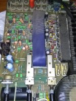
On further investigation, I noticed that there are some visual damaged components:
RV2 and RV3 seem blown. Could this be just the culprit? What more to look for?
I attached some photos, sorry about all the dust...
I have a bulb lamp voltage limiter connected 🙂
I did the voltage tests on the power supply and all they tested ok.
On further investigation, I noticed that there are some visual damaged components:
RV2 and RV3 seem blown. Could this be just the culprit? What more to look for?
I attached some photos, sorry about all the dust...
Attachments


RV2/3 look OK to me. The varnish is to stop the value moving. They are pre sets. Cyrus 2? Doesn't look like the one I know.
Cyrus 2 doesn't have pre sets!
Cyrus 2 doesn't have pre sets!
Oh, that's varnish... bummer...
It is the first version of Cyrus two, "Issue 06" with the plastic case.
I followed the signal path to the power amplifier and seems ok.. only had some resistors on it's path..
It is the first version of Cyrus two, "Issue 06" with the plastic case.
I followed the signal path to the power amplifier and seems ok.. only had some resistors on it's path..
Those large brown capacitors are known to get bad (from what I saw on the web), could they be the culprit for all things wrong?
Cyrus 2? Doesn't look like the one I know.
Cyrus 2 doesn't have pre sets!
This is a very old version.
I doubt it. Yes, these Roedersteins are known for cracking and then drying out, but that wouldn't mess things up like what you're seeing.Those large brown capacitors are known to get bad (from what I saw on the web), could they be the culprit for all things wrong?
I'd say give the thing a good cleaning and start poking around with the multimeter. Fuse continuity, shorted output transistors or drivers (basic santify checks using diode test), ground continuity, stuff like that. Then measure power amp supplies at the fuses, you should have found a grounded spot to measure against at this point.
One more thing you could do is verify that the phono stage works over the rec-out. Then your +/-15V supplies are probably good.
The brown ROE caps like to go open circuit which messes up the feedback loop of the power amp. Replace them with good quality 470uF capacitors, ideally nonpolarised ones, but regular electrolytics with at least 25v rating will do.
The output transistors often fail in this amplifier when the amp is pushed too hard. They are labelled PT7, which is actually a BUV28 remarked. Unfortunately the BUV28 is now obsolete too.
The output transistors often fail in this amplifier when the amp is pushed too hard. They are labelled PT7, which is actually a BUV28 remarked. Unfortunately the BUV28 is now obsolete too.
In a sitn like this where you don't have a protect circuit (and where the problem isn't easily detectable), start with assessing power is going to where it should - it looks like you have confirmed this?
Next step is start testing semiconductors working back from the outputs. If you have nothing thru the speakers this indicates a catastrophic semiconductor failure (as you don't have a relay to test in this circuit). Pull the outputs one by and one and test for continuity and report back.
Altho there are parts in there now obsolete, you MAY be able to replace those where you cant obtain the originals with modern equivalents. There are a shite-load of transistors in there to test, so let us know how you go with the outputs!
In a sitn like this where you don't have a protect circuit (and where the problem isn't easily detectable), start with assessing power is going to where it should - it looks like you have confirmed this?
Next step is start testing semiconductors working back from the outputs. If you have nothing thru the speakers this indicates a catastrophic semiconductor failure (as you don't have a relay to test in this circuit). Pull the outputs one by and one and test for continuity and report back.
Altho there are parts in there now obsolete, you MAY be able to replace those where you cant obtain the originals with modern equivalents. There are a shite-load of transistors in there to test, so let us know how you go with the outputs!
All transistor and output tests must be done with part out of board? I have to desolder them to do continuity tests?
The PT7 output transistors are in parallel pairs, 4 per channel. You cannot test individual transistors when they are in parallel so removal of at least one transistor of each pair is necessary to check for essentials like a Collector-Emitter short or the base emitter voltage (Vbe). For a complete test of all possible faults, you certainly have to remove any TO220 transistors.All transistor and output tests must be done with part out of board? I have to desolder them to do continuity tests?
Sorry about tell you guys I had no sound in speakers, there is sound although it does not seem the right volume.
One channel has better quality and higher volume, the other has lower and lower quality.
What I hear of noise is some artifacts like it happens with digital tranmission with poor quality or cell phones with bad cover, I made a small audio file to show that.
I changed the two bakelite capacitors and there was no change in anything. Should I replace all other capacitors first?
Do I really need to use bipolar capacitors? They are hard to find locally..
https://drive.google.com/file/d/0B6_qlViKEJhVTER3NnRCWWF4cjAzcTlMT2RvY1RrSkQ0Y3d3/view?usp=sharing
or here:
 Voz_161206_1 by Sérgio Moura, on Flickr
One channel has better quality and higher volume, the other has lower and lower quality.
What I hear of noise is some artifacts like it happens with digital tranmission with poor quality or cell phones with bad cover, I made a small audio file to show that.
I changed the two bakelite capacitors and there was no change in anything. Should I replace all other capacitors first?
Do I really need to use bipolar capacitors? They are hard to find locally..
https://drive.google.com/file/d/0B6_qlViKEJhVTER3NnRCWWF4cjAzcTlMT2RvY1RrSkQ0Y3d3/view?usp=sharing
or here:
Voz_161206_1 by Sérgio Moura, on Flickr
Last edited:
The recording does sound like an output transistor fault but there are other possibilities for distorted sound like that so I can't be certain without proper tests.
A good thing to check just in case would be continuity between R67/68/69/70 ground side and small-signal ground at power amp input, at the volume pot and at the inputs. Things are not going to work well if there's a break in there somewhere. Likewise, verify continuity from 470 µF caps to Q9/10 base. And of course, make sure the actual signal doesn't get lost in transit.
Assuming your multimeter is OK to less than about half an ohm, rough in-circuit testing even of your output transistors should be feasible. Speaking of half an ohm, do check the 0R47 power resistors.
Assuming your multimeter is OK to less than about half an ohm, rough in-circuit testing even of your output transistors should be feasible. Speaking of half an ohm, do check the 0R47 power resistors.
A good thing to check just in case would be continuity between R67/68/69/70 ground side and small-signal ground at power amp input, at the volume pot and at the inputs. Things are not going to work well if there's a break in there somewhere. Likewise, verify continuity from 470 µF caps to Q9/10 base. And of course, make sure the actual signal doesn't get lost in transit.
Assuming your multimeter is OK to less than about half an ohm, rough in-circuit testing even of your output transistors should be feasible. Speaking of half an ohm, do check the 0R47 power resistors.
I got a bit lost on checking continuity on those resistors, can you please explain a bit more?
The resistors at the output did test ok on my cheap multimeter.
On the fuse I should have 41V but I get 38.6v, is this still ok?
The two regulators that feed the pre-amplifier are quite hot, in fact, their heatsink is almost un-touchable hot, could this be normal? (their voltages checked ok)
The capacitors just before those regulators are not the original, so at some point there has been done a repair on this amp...
I am feeling a bit lost, should I first change all capacitors our should I start removing transistors and testing them one by one?
- Home
- Amplifiers
- Solid State
- Mission Cyrus Two - help identify what's wrong..