Modifying Monitor Audio Bronze BX2 Speakers (2010-2015yr model).
Part 1 of 7
I completed this project in December 2020, & submitted a shorter version of this write up in July 2021 to the blog of the web shop that I purchased the capacitors, resistors, & inductors from.
Monitor Audio Bronze BX2 Speaker Upgrade | HIFICollective
The following writeup is a “reference page”, more in-depth & contains the parts list.
Disclaimer:-
I do not have any microphones or sound measuring equipment, so no charts/measured tests have been carried out. I am only going by what my hearing tells me. I am qualified in certain aspects of electrical design & have actual hands-on experience on various builds from PCs, Hi-fis, cars, houses, & at one time I worked for the local electricity company!
Intro:-
“To modify or replace”, that is the question I recently asked myself, regarding the Monitor Audio Bronze BX2 (2010-2015yr model) speakers that I purchased new back in 2013. These speakers were highly acclaimed when they came out, & still sounded good. However, being very picky, they suffered from bass boom/resonance via the cabinet, occasional sharp highs & a slightly muddy midrange, with the sound distinctly coming from two speakers & not a wide “soundstage”. This despite toeing them in, moving them away from the walls, bi-wiring them, & trying various other well-known mods & obscure tricks!
I did an extensive amount of research on the web, some info from this forum, some from the blogs on Hi-Fi Collective (especially the one by P.A. Coupe who is Reference Fidelity Components), the huge reference website of humblehomemadehifi.com, & a few others. I was also spurred on after watching videos posted by G.R. Research on YouTube, who analyse numerous main brand speakers with the proper test equipment, then upgrade the crossovers etc. & then retest them. Many times, the expensive speakers have cheap crossover parts, & cheap speakers after modification, can produce better results than the expensive speakers in unmodified format! Many of the modifications I carried out are well known & essential for any decent speaker build/modification. However, some are less well known & others I deviated away from convention!
Some of the design considerations:-
- Keep the crossovers the same design, as I wanted to verify that improving the quality of components, without changing values or crossover design/type, would alter the sound for the better, hopefully! Also, I do not have a calibrated stand microphone & suitable measuring software. This being the best way to fine tune crossover component values using actual sound measurements from the drivers.
- No more than £20 to be spent on any single capacitor, resistor, or inductor.
- Make the internal cables easily removable from the board & back panel connectors, as per the original crossover.
- Reduce extraneous metal from the signal path where possible, especially from the binding posts!
- Internal cables & inductor wire gauges to be equal to or thicker than the component leads, with the LF inductor being thicker wire gauge than the HF inductor.
- Remove other traits from the components, i.e., inductors to have low resistance, resistors to have low inductance, capacitors to have low ESR.
- Tighter component value tolerances, i.e., 1% or 3% at most, instead of 5% or 10%.
- All electrical contacts to be non-magnetic (to reduce other “influences”), brass or oxygen free copper, & gold plated, if possible.
- Solder used to be lead free silver solder (tin/silver/copper by Shenmao).
- All fixings to be non-magnetic, & stainless steel, to reduce other “influences”.
- Reinforce, deaden & remove resonances from cabinets.
- Make the modifications look “factory” or better than “factory”.
Last edited by a moderator:

Part 2 of 7
Speaker Details:-
The cabinet itself has radiused front vertical edges, close spacing of the tweeter to the mid/bass driver & is front ported, with a large plastic panel on the rear for the four bi-wiring binding posts.

Inside the cabinet there were four blocks reinforcing the corners on the front panel, & one block on the full height figure of 8 brace mid depth in the cabinet. However, the back panel was not corner reinforced, & the cabinet was made using thin 15mm MDF. Grey foam sheet, 35mm thick, was used in the front section as sound damping & was stuffed around the mid/bass driver basket suffocating it, which is not good!! The crossover was mounted internally & high up on the rear panel.

Of note is the unusual way the mid/bass driver is mounted, via a long furniture assembly bolt, through the back panel & into a threaded hole in the back centre of the driver/magnet. This supporting the driver’s heaviest mass & actually clamping the front & back panels together. However, the tightness of the bolt is critical as it affects the sound!

The 165mm mid/bass C-CAM (ceramic coated aluminium/magnesium material) drivers, marked 3 Ohm, have an ABS/polycarbonate basket, vented voice coil, shielded magnet, butyl rubber surround, & a pseudo phase plug/dust cap. The 25mm C-CAM, gold anodised dome tweeters, marked 4 Ohm, are fully back sealed. The drivers being better quality than I thought, in perfect condition & warranted keeping!

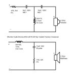
I manged to get the inductor values & crossover frequency (3.2kHz) in a technical drawing from Monitor Audio (I attach my redrawn version).

The crossover LF section is a 1st Order with Zobel network, & has an iron cored inductor, bi-polar electrolytic capacitor & a resistor. The HF section is a 3rd Order with a single series resistor beforehand (basic L-pad), & has an air cored inductor & MET poly caps. Both inductors were placed at 90deg to each other. However, basic sand cast resistors, & thin wire inductors were used, & the internal wiring was only 18AWG, with the components tightly packed onto a small board. Overall, good construction & decent speaker components were used, considering they retailed for only £250-£290 a pair!

Speaker Details:-
The cabinet itself has radiused front vertical edges, close spacing of the tweeter to the mid/bass driver & is front ported, with a large plastic panel on the rear for the four bi-wiring binding posts.
Inside the cabinet there were four blocks reinforcing the corners on the front panel, & one block on the full height figure of 8 brace mid depth in the cabinet. However, the back panel was not corner reinforced, & the cabinet was made using thin 15mm MDF. Grey foam sheet, 35mm thick, was used in the front section as sound damping & was stuffed around the mid/bass driver basket suffocating it, which is not good!! The crossover was mounted internally & high up on the rear panel.
Of note is the unusual way the mid/bass driver is mounted, via a long furniture assembly bolt, through the back panel & into a threaded hole in the back centre of the driver/magnet. This supporting the driver’s heaviest mass & actually clamping the front & back panels together. However, the tightness of the bolt is critical as it affects the sound!
The 165mm mid/bass C-CAM (ceramic coated aluminium/magnesium material) drivers, marked 3 Ohm, have an ABS/polycarbonate basket, vented voice coil, shielded magnet, butyl rubber surround, & a pseudo phase plug/dust cap. The 25mm C-CAM, gold anodised dome tweeters, marked 4 Ohm, are fully back sealed. The drivers being better quality than I thought, in perfect condition & warranted keeping!
I manged to get the inductor values & crossover frequency (3.2kHz) in a technical drawing from Monitor Audio (I attach my redrawn version).
The crossover LF section is a 1st Order with Zobel network, & has an iron cored inductor, bi-polar electrolytic capacitor & a resistor. The HF section is a 3rd Order with a single series resistor beforehand (basic L-pad), & has an air cored inductor & MET poly caps. Both inductors were placed at 90deg to each other. However, basic sand cast resistors, & thin wire inductors were used, & the internal wiring was only 18AWG, with the components tightly packed onto a small board. Overall, good construction & decent speaker components were used, considering they retailed for only £250-£290 a pair!
Last edited by a moderator:
Part 3 of 7
Modifications to the Cabinets:-
All components & sound damping were removed & all internal surfaces cleaned. Primed the MDF with diluted PVA, let dry, & applied Dynamat self-adhesive bitumen sound deadening sheets to cover the middle half of each section on each side & the back panel of the cabinet. I then made & glued three more wooden blocks to reinforce the corners on the full height figure of 8 brace. Pine quadrant beading (12mmx12mm) was glued to reinforce the whole way around the inside of the back panel, & parts of the front panel.


The sides, top, rear, & bottom panels were lined & glued (PVA) with standard 35mm thick white polyester wadding. The sides immediately next to the mid/bass driver & the bottom near the port were not lined to allow free air flow.

The highly magnetic furniture assembly bolt that fixes the mid/bass driver to the cabinet, was remade using a longer non-magnetic stainless-steel bolt, cut down, with a matching washer. When fitted, correct tightening is:- tighten to seat driver, holder driver in place, then undo just enough to cause the bolt to be loose, then re-tighten until it just stops wiggling then tighten a further 90deg turn.

Modifications to the Cabinets:-
All components & sound damping were removed & all internal surfaces cleaned. Primed the MDF with diluted PVA, let dry, & applied Dynamat self-adhesive bitumen sound deadening sheets to cover the middle half of each section on each side & the back panel of the cabinet. I then made & glued three more wooden blocks to reinforce the corners on the full height figure of 8 brace. Pine quadrant beading (12mmx12mm) was glued to reinforce the whole way around the inside of the back panel, & parts of the front panel.
The sides, top, rear, & bottom panels were lined & glued (PVA) with standard 35mm thick white polyester wadding. The sides immediately next to the mid/bass driver & the bottom near the port were not lined to allow free air flow.
The highly magnetic furniture assembly bolt that fixes the mid/bass driver to the cabinet, was remade using a longer non-magnetic stainless-steel bolt, cut down, with a matching washer. When fitted, correct tightening is:- tighten to seat driver, holder driver in place, then undo just enough to cause the bolt to be loose, then re-tighten until it just stops wiggling then tighten a further 90deg turn.
Last edited by a moderator:
Part 4 of 7
New Crossover Network & Box:-
In order to space the components further apart, away from the drivers for less interference, & to cover the hole left by the binding post panel, a suitably large flame proof ABS box made by Hammond was chosen to mount externally on the rear panel.

The capacitor/inductor/resistor brands (ClarityCap, Jantzen, & Mills) were chosen as they repeatedly get good reviews, plus the caps were made in the UK where I am! The 250V CSA & ESA caps were chosen as both have a similar construction, low ESR, 3% tolerance, with the cheaper ESA version as the mid/bass shunt cap. Unfortunately, I couldn’t find a 6uF cap so had to parallel a 2.7uF & 3.3uF on the HF section! Due to the high 3.2kHz crossover point, I chose Jantzen air core inductors with a low DCR of 1/20th of the respective driver stated impedance & placed them at 90deg to each other with at least 10cm of separation. The AWG of the new LF coil was 14AWG with 18AWG for the HF, this up from 18AWG & 21AWG respectively! The Mills resistors were chosen due to low inductance & are the 12w 1% tolerance versions.
I mounted all the components on a sheet of flame resistant, no holes/no clad, FR-4 PCB board, using the correct neutral cure clear silicone sealant & heat proof cable ties. I made certain in the design of the layout that I was able to join all the components directly to one another’s leads & soldered.


For the main cable connections on the PCB, a M4 brass machine screw with a stainless steel serrated washer was placed through from the reverse side of the PCB board & a stainless steel serrated flanged nut was screwed down tight from the front side making a fixed “stud”. A plain stainless steel washer was placed over this, then the capacitor/resistor/inductor lead was wound once around the stud, then the cable M4 eye(s) were placed over, then another s/s serrated flanged nut is used to clamp everything together. This making maximum clamped surface area contact, as used in many other electrical situations!


Plastic spacers, 10mm high, were glued (Superglue) to the underside of the PCB board for clearance of the screw heads & cable ties. Six mushroom head wood screws were used to go through the PCB board, spacer & the ABS box, to securely fix the whole lot to the back panel of the speaker. A small sleeve of heat shrink was used around the top of the screw shank to fill out the tolerance gap between the screw & the inside of the plastic spacer.

The rear face of the ABS box has a wide strip of thin felt (self-adhesive on one side) Tessa tape, to air seal the box to the speaker panel. Where the cables go through the ABS box into the speaker, I made a big felt sleeve to air seal them.

For internal wiring I used silicone insulated, 1000V, “test/measurement” OFC multistrand wire called “Silivolt-1V” made by MC/Staubli as its highly flexible & soldering iron resistant. Initially I used the 0.75mm CSA version, it being a similar CSA to the original 18AWG wiring, & to test a theory regarding cable CSA. These cables were terminated at one end with tinned M4 eyes with grips & tinned push tabs at the other. The wire was tinned & connecter was crimped, & all had clear heat shrink sleeving over them. (Later on, all the internal cables were “upgraded” & remade, see “Further modifications”)

I used MC/Staubli, gold plated brass connection, 4mm diameter shrouded test/measurement back panel sockets (with 6.3mm push tabs) on the box lid. The existing external speaker cables to the amp received the matching MC/Stabuli gold plated brass 4mm plugs & the cable ends were tinned/crimped/soldered. These 4mm test connectors were chosen as they have very little extraneous metal in them (compared to the previous Furutech ones), are non-magnetic & as these & the above cables are used in highly sensitive electronic test equipment, surely, they’re good enough for this use?!


New Crossover Network & Box:-
In order to space the components further apart, away from the drivers for less interference, & to cover the hole left by the binding post panel, a suitably large flame proof ABS box made by Hammond was chosen to mount externally on the rear panel.
The capacitor/inductor/resistor brands (ClarityCap, Jantzen, & Mills) were chosen as they repeatedly get good reviews, plus the caps were made in the UK where I am! The 250V CSA & ESA caps were chosen as both have a similar construction, low ESR, 3% tolerance, with the cheaper ESA version as the mid/bass shunt cap. Unfortunately, I couldn’t find a 6uF cap so had to parallel a 2.7uF & 3.3uF on the HF section! Due to the high 3.2kHz crossover point, I chose Jantzen air core inductors with a low DCR of 1/20th of the respective driver stated impedance & placed them at 90deg to each other with at least 10cm of separation. The AWG of the new LF coil was 14AWG with 18AWG for the HF, this up from 18AWG & 21AWG respectively! The Mills resistors were chosen due to low inductance & are the 12w 1% tolerance versions.
I mounted all the components on a sheet of flame resistant, no holes/no clad, FR-4 PCB board, using the correct neutral cure clear silicone sealant & heat proof cable ties. I made certain in the design of the layout that I was able to join all the components directly to one another’s leads & soldered.
For the main cable connections on the PCB, a M4 brass machine screw with a stainless steel serrated washer was placed through from the reverse side of the PCB board & a stainless steel serrated flanged nut was screwed down tight from the front side making a fixed “stud”. A plain stainless steel washer was placed over this, then the capacitor/resistor/inductor lead was wound once around the stud, then the cable M4 eye(s) were placed over, then another s/s serrated flanged nut is used to clamp everything together. This making maximum clamped surface area contact, as used in many other electrical situations!
Plastic spacers, 10mm high, were glued (Superglue) to the underside of the PCB board for clearance of the screw heads & cable ties. Six mushroom head wood screws were used to go through the PCB board, spacer & the ABS box, to securely fix the whole lot to the back panel of the speaker. A small sleeve of heat shrink was used around the top of the screw shank to fill out the tolerance gap between the screw & the inside of the plastic spacer.
The rear face of the ABS box has a wide strip of thin felt (self-adhesive on one side) Tessa tape, to air seal the box to the speaker panel. Where the cables go through the ABS box into the speaker, I made a big felt sleeve to air seal them.
For internal wiring I used silicone insulated, 1000V, “test/measurement” OFC multistrand wire called “Silivolt-1V” made by MC/Staubli as its highly flexible & soldering iron resistant. Initially I used the 0.75mm CSA version, it being a similar CSA to the original 18AWG wiring, & to test a theory regarding cable CSA. These cables were terminated at one end with tinned M4 eyes with grips & tinned push tabs at the other. The wire was tinned & connecter was crimped, & all had clear heat shrink sleeving over them. (Later on, all the internal cables were “upgraded” & remade, see “Further modifications”)
I used MC/Staubli, gold plated brass connection, 4mm diameter shrouded test/measurement back panel sockets (with 6.3mm push tabs) on the box lid. The existing external speaker cables to the amp received the matching MC/Stabuli gold plated brass 4mm plugs & the cable ends were tinned/crimped/soldered. These 4mm test connectors were chosen as they have very little extraneous metal in them (compared to the previous Furutech ones), are non-magnetic & as these & the above cables are used in highly sensitive electronic test equipment, surely, they’re good enough for this use?!
Last edited by a moderator:
Part 5 of 7
Initial Results:-
The speakers were placed exactly as they were previously & the rest of the music chain is exactly as before, i.e., modified Denon D-F109DAB system (receiver, CD player, network player), with short length (3m max) modified Atlas Equator MKII OFC bi-wire speaker cable.
After several weeks of playing lots of different music through them I can confirm that all the above modifications to the speakers have drastically improved the sound! The work to the cabinet has removed all bass boom/resonance, which was to be expected. The high frequency notes are much clearer, & less sharp/tiring on the ears, the mid-range is no longer muddy & there is now a proper soundstage! The best part is when low kick drums with either a bass guitar or a double bass are playing along, you can now tell each separate note, instead of hearing a combined muddy note! The notes are faster & cleaner as the drivers can react much quicker than before, & with no unnecessary “overrun bounce”. All this clarity is available with the 65W class D amp volume set to 10%, so low volume levels are very good, let alone the higher volume levels!! The modifications increased the weight of each speaker from a stated 5.84Kg to circa 6.4Kg.
Music Used:-
Massive Attack, Miles Davis, Antonio Forcione, Enigma, DMX, The Hu, The Ramsey Lewis Trio, Harry James, Dave Brubeck, Eagles, The Glitch Mob, Magnificat (Thomas Tallis), various classical recordings, & many others! By record labels such as:- Columbia Legacy, Blue Note, Sheffield Labs, Naim, Linn, Deutsche Grammophon, etc..
Music is either original CD, FLAC ripped from said CD (using dBpoweramp software), or purchased FLAC download files from the record label, in resolutions as high as 24bit 192kHz studio remasters. This last format I purchased in 2015 of the highly acclaimed “Meet Me in London” album by Antonio Forcione with Sabina Sciubba on vocals. To say it now sounds astounding with the modified speakers is an understatement - you can now hear the pins drop in the recording studio, let alone “be there”!!
Last edited by a moderator:
Part 6 of 7
Further Modifications:-
As I initially used 0.75mm CSA (18AWG) cable I did notice that the much lower bass/drum notes, although very clear, lacked body, or “oomph”. So, I remade all the internal wiring with the thicker 2.5mm CSA (13AWG) version & retested. Now the lower drums & bass guitars had the required conviction they needed without sounding “boomy”! I did not notice any difference to the mid or higher frequency notes with this cable swap, which was to be expected. As the maximum total length of internal wiring on any driver is 800mm, the resistance of the 0.75mm CSA is therefore 0.0208 Ohm, & on the 2.5mm CSA its 0.006384 Ohm, according to the manufacturer’s data sheets. These seem insignificant amounts, but there is an audible difference!
When I remade the cables, I now used Molex OFC M4 tinned eyes without cable sheath grips at one end, & gold-plated push tabs at the other end. The wire ends were tinned & connectors were crimped as before. However, now I fed solder into the wire/crimp. All ends again have clear heat shrink sleeving over them. Again, the push tab ends were all carefully compressed to be a proper tight fit on the speaker tabs, due to “odd” sizing on the driver tabs.


I also shortened some of the longer brass screw “studs” on the PCB board. These alterations to lessen the amount of unnecessary metal in the signal chain even further. I have also altered the positioning of the wadding near the drivers & port, several times to fine tune the “slam/attack” of lower notes.

Further Modifications:-
As I initially used 0.75mm CSA (18AWG) cable I did notice that the much lower bass/drum notes, although very clear, lacked body, or “oomph”. So, I remade all the internal wiring with the thicker 2.5mm CSA (13AWG) version & retested. Now the lower drums & bass guitars had the required conviction they needed without sounding “boomy”! I did not notice any difference to the mid or higher frequency notes with this cable swap, which was to be expected. As the maximum total length of internal wiring on any driver is 800mm, the resistance of the 0.75mm CSA is therefore 0.0208 Ohm, & on the 2.5mm CSA its 0.006384 Ohm, according to the manufacturer’s data sheets. These seem insignificant amounts, but there is an audible difference!
When I remade the cables, I now used Molex OFC M4 tinned eyes without cable sheath grips at one end, & gold-plated push tabs at the other end. The wire ends were tinned & connectors were crimped as before. However, now I fed solder into the wire/crimp. All ends again have clear heat shrink sleeving over them. Again, the push tab ends were all carefully compressed to be a proper tight fit on the speaker tabs, due to “odd” sizing on the driver tabs.
I also shortened some of the longer brass screw “studs” on the PCB board. These alterations to lessen the amount of unnecessary metal in the signal chain even further. I have also altered the positioning of the wadding near the drivers & port, several times to fine tune the “slam/attack” of lower notes.
Last edited by a moderator:
Part 7 of 7
Conclusions:-
These modifications prove that the sound the driver is producing is only as good as the signal that it receives. If the components in the signal path are of a basic standard, then the sound produced by the driver will be compromised, regardless of the driver quality. It also proves yet again, that mid/bass drivers require thicker CSA cable to provide the necessary power to move them properly!
The hardest parts of the build were component selection/sourcing, design/configuration of the board, accurately cutting/drilling the FR-4 board, altering the gold-plated push tabs to tightly fit the odd sizes on the driver terminals, & making 16 cables crimped & soldered on both ends…twice!! Total cost for all components is at least £395 & possibly up to £450, as I already had PVA glue, felt, solder, cable ties, bitumen sound deadening sheets, & wood blocks.
Many people would consider spending £400-£450 to modify a set of 8yr old speakers which originally cost £250-£290, as utter madness. However, having seen the test results, insides & crossovers, of some expensive similar sized speakers, I doubt you could get the same sound quality from a set of new “off the shelf” speakers without spending at least £1,500.
For those who want to replicate what I have done, I attach the parts list as a PDF file below.
Attachments
Last edited by a moderator:
Good job Dave.
I recently picked up a 2nd hand pair with the intention of replacing the stock crossover parts with better quality ones.
I put in some bituminous tape in the most corners and the hole where the round speaker terminal assembly was located.
I build an external box with multiplex and put some veneer on it.
I replaced ALL wiring with Teflon tape wrapped solid core 1.5mm2 copper wire, , each paralleled with a Teflon tape wrapped 0.5mm2 solid core silver wire. No connectors, everything soldered with 3.5% silver solder.
I focused mostly on the series components, reusing parts in the parallel sections:
Woofer:
JANTZEN AUDIO 000-0010 4N Copper Air Core Wire Coil 14AWG 0.47mH 52x30mm DCR: 0.164 ohms. Removed a few turns reducing it to 0.45 mH
10u electrolyte capacitor in the shunt position replaced by the salvaged 10u MKT from the original crossover tweeter section
1.5 ceramic resistor reused in the shunt position
Tweeter:
1.5 ceramic resistor replaced by:
MUNDORF MRESIST ULTRA Resistor 30W 1.5 Ohm
6 u capacitor replaced by paralleling:
JANTZEN AUDIO SUPERIOR Z-CAP Capacitor 800V 3.3μF
JANTZEN AUDIO SUPERIOR Z-CAP Capacitor 800V 2.7μF
CORNELL DUBILIER 940C Film Capacitor 3000V 0,01µF (Tony Gee)
10 u capacitor replaced by paralleling:
Mundorf MCap supreme 10u (about same level as the Jantzen, but less expensive due to second hand deal)
CORNELL DUBILIER 940C Film Capacitor 3000V 0,01µF (Tony Gee)
Shunt position 0.15 mH air coil reused
Round speaker terminal assembly reused
Very pleasantly surprised (I actually never listened to them stock).
Really nice deep & tight bass, slightly warm (compared to my main monitors), no harshness in the treble.
Quite a bit of space and air.
Total cost Euro 210 for the speakers with stands, and about an additional Euro 200 for all parts
Can send you some pictures if you send me a PM with your email address.
Recently picked up a mint pair of these for $75. Thinking of some crossover upgrades, but would like to keep costs to a minimum and fit everything in the existing cabinets. I made some changes/upgrades in a pair of ELAC UniFi UB51s (Not really noticeable) and My Klipsch RP600Ms (more successful). As I've always read that components in the signal path are audible. it would seem that swapping in expensive parts in the zoebel would be somewhat pointless. I also have a couple questions about wire gauge and bypass caps.
Many people would upgrade internal wiring to higher quality, larger gauge as an upgrade. For something like the tweeter circuit, where the first component in the signal path is a tiny wire gauge resistor, is there really any gain? You can use 14 gauge internal wiring, but soldering that to a 22 gauge lead on a mills resistor seems somewhat pointless. Like a firehose going to a small garden sprayer.
The Original Inductor in the woofer circuit is an iron core, 18 or 19 gauge. As this speaker has a high 3200 Hz crossover point, it would seem this would be an obvious point to improve. My question is, "is the biggest improvement from getting rid of the iron and going to an aircore, or is it from a larger gauge inductor?" I can get Jantzen aircore inductors in either 18 or 15 gauge, but the 18 is much easier to swap onto the existing crossover board.
Has anyone tried adding bypass caps to the original polyester caps in the tweeter circuit rather than swapping in expensive, and physically much larger polypro caps? Cornell Dubilier 940C, Vishay 1837, Russian K40Y9 PIO or similar in a 0.01Uf value? The original 6Uf is an odd value and pretty much requires running 2 physically large caps in parallel in order to get that value. This is nearly impossible to fit if you are trying to upgrade the original board.
I would like to upgrade, without building an external crossover, or adding so much inside the box that it reduces the internal volume enough to matter acoustically.
Powering these with my ARCAM Diva 350 which is 130watts/channel into 2, so power isn't an issue.
Attachments


@speedmadness, If you want to reuse the existing board in its existing place, & thus keep costs down, I had thought of this scenario!
I would remove all the components from the original board & replace with better ones that fit in the spaces.
I would remove all the components from the original board & replace with better ones that fit in the spaces.
- You could use the Mills resistors or similar, you might have to have them standing up from the board instead of glued flat due to their length, but please bin the cheap resistors!
- The electrolytic cap, use 105C full size Panasonic Audio grade caps, or similar which would be a direct fit, but much better than the originals.
- The MET Poly caps, again you should be able to fit a better cheap set of similar size.
- The inductors, you would have to use an iron cored for the bass/mid section, but you should be able to fit one that has a thicker wire. The tweeter section, keep to air cored, but again use one with a thicker wire.
- Cables, you could leave the tweeter section cable alone, but you need to use thicker cables on the bass/mid section.
@speedmadness ...I attach as a JPEG the specs & existing component dimensions & hole spacing for the factory X-over. This should help you when looking for parts when reusing the factory PCB. I also re-attach my photo of the factory Monitor Audio X-over from the BX2 speakers.


Is there a trick to removing the metal grill on the tweeter? I don't want to damage it while removing it to access the mounting screws.
@speedmadness ...I used my metal dental picks with an angled end.....insert into a hole near the outer edge & ease the grille out...& do it several times around the grille.
This end type worked the best for me:-

This end type worked the best for me:-
- Home
- Loudspeakers
- Multi-Way
- Modifying Monitor Audio Bronze BX2 Speakers (2010-2015 yr model)