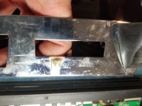
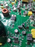
Hello everyone. I have a mtx 1501d that is in protect mode. I am a seasoned tech and work on a ton of home audio gear but am very new to auto amplifiers. I would like to get this thing up and running. I cant find a service manual for this amplifier and am hoping I can use this amp to get me more familiar with auto amplifiers. I popped the top and found four HUF75339P that have been destroyed. Looking at the speaker terminal strips it appears someone was wiring subs up to this amp while it was on and shorted one of the wires to the case ( arc marks on the case). Nothing else in the amp looks visually bad. I ohmed out all the ouput transistors and they dont appear to be shorted. Il post a couple pics. Are these fets still in production or are you guys using modern replacements? I work on a ton of vintage amplifiers and allmost allways need modern replacement. Anyhow if you guys can kind of give me some tips or help with this that would be awsome. I will post a couple pics and look forward to hearing from you guys.
Attachments


Last edited:
After further investigation I found r435 is allmost fully open and d198 was very hot. It doesnt seem to test shorted or open but I wont know till I remove it.
D198 WAS hot or IS hot?
I use IRF3205 FETs in the supply but the originals are still available from digikey and mouser (and others).
Do you still have a good drive signal going into the open gate resistor?
I use IRF3205 FETs in the supply but the originals are still available from digikey and mouser (and others).
Do you still have a good drive signal going into the open gate resistor?
There is no reason for it ever to get hot unless the amp loses the main ground and then the amp tries to ground through the RCA shields. Remove it and leave it out.
Do you have any other FETs to install in the power supply?
Did the other 4 FETs survive in the PS?
Do you have any other FETs to install in the power supply?
Did the other 4 FETs survive in the PS?
Gotchya. The other fets test ok in circuit. I doubt I have any replacements on hand to replace the ones that went boom.
Last edited:
Move 2 of the survivors to the other bank (after removing all of the failed FETs) and replace the burned gate resistor and see if it will power up.
To disable the output stage, jump the capacitor in the image below. The wire is cut but that was simply to re-enable the output. You want to be very careful with the outputs, especially if they're the ones that are no longer available.
Tightly clamp all semis to the heatsink before applying power.
To disable the output stage, jump the capacitor in the image below. The wire is cut but that was simply to re-enable the output. You want to be very careful with the outputs, especially if they're the ones that are no longer available.
Tightly clamp all semis to the heatsink before applying power.
Attachments

Understood. I should be able to do that later on this evening. I dont have any surface mount resistors on hand as I work mainly in the vintage world. I'm sure a 1/4 watt axial resistor wouldn't hurt it temporarily to make sure this thing isn't destroyed before ordering parts. In the kind of repair work I do I use a dim bulb tester and or variac to limit current or voltage to save myself from ruining more parts during diagnoses. Is there anything you guys use in this type of work to limit the amperage or is it simple not necessary? Right now I have my battery charger plugged into my dbt with a small wattage bulb as i have no clue about the circuitry involved in these kind of amps. Also thank you very much for the help it is much appreciated.
Current limiting can cause problems. That said, you don't want unlimited current. For this amp, I'd insert a 15 amp ATC/ATO fuse in the B+ line and use a supply that's rated for at least 25 amps. With the FETs clamped to the heatsink, it's very difficult to damage them, especially when clamped and using the fuse.
In general, you will use a current limiting resistor (won't work for all amplifiers). A 1 or 2 ohm 100W cylindrical wirewound resistor is my preference. Having a 12v buzzer across a 2 ohm resistor is helpful in that it give an audible indication of the current flow.
DBT?
Battery charger? What type?
In general, you will use a current limiting resistor (won't work for all amplifiers). A 1 or 2 ohm 100W cylindrical wirewound resistor is my preference. Having a 12v buzzer across a 2 ohm resistor is helpful in that it give an audible indication of the current flow.
DBT?
Battery charger? What type?
A dbt is a dim bulb testor. The hot lead in your 120 mains goes throught a light bulb filament then off to an outlet. The bigger the bulb the more current can pass through it. If somthing is dead shorted the bulb lights up limiting destruction to other parts of the amplifier. I just had a 2 amp trickle charger on there to see if I had the drive signal for the fets you were asking about. I can easily set up a fused lead to power it up after moving those fets to the other bank for testing. I'm just super unfamiliar and playing it safe is all. Somtimes knowing a little can be worse then not knowing anything ahhaha. I have plenty of big amp variable dc power supplies on hand so no issue there.
It's good to be safe but you have to realize that the power supply in this amp will pass 100+ amps of current during normal operation and as long as the FETs are clamped, it's very difficult to hurt them, especially with a fuse inline.
The outputs in some of these amps are discontinued/obsolete and the amps don't work well with any other FETs without modification. This typically applies to the outputs without individual gate resistors. The ones with individual gate resistors (which are different for the high and low-side) are a bit more tolerant but leave them clamped. The jumper will keep them out of operation so they're fairly safe.
The regulator and the switching transistor near the small transformer can overheat and fail and cause a lot of damage so leave them clamped as well.
The incandescent lamps are very commonly used with mains techs and can work for smaller amps but not well for amps that draw a lot of current. This amp will likely draw 25+ amps at start with uncharged rail caps. After they charge, it will start with less.
For some car amps, you would use a 120v incandescent lamp on the secondary to help protect the outputs.
Car amps are a completely different world.
How vintage is the stuff you typically work on? '70s? Old pioneer and that sort of stuff? Or tube equipment?
Yes I mainly work on the early transistor amps up to modern but usually the old gear. Pioneer, sansui, carver, and so on. I know these are a completely different world, that's why I'm here asking before I get ahead of myself. I moved them fets, replaced the resistor and had to replace the capacitor in front of fet 439 because it was bad I think just from the heat . Anyhow my amp looks slightly different then the one you pictured. Is the circled capacitor the right one to jump?
Attachments

As far as I know, that's the same capacitor. Your amp has the FET that's used to discharge the rail caps. Connected between pin 8 of the 339 and ground?
I didn't work on home equipment more than a few years but it always amazed me of how poorly the regulators were designed. There were so many that ran so hot that the boards were destroyed. I generally had to move them, most often onto the main heatsink. It sometimes happens in car amps as well. The simplest part of the amp and they can't get it right.
The old Pioneers and Sansuis were nice. I saw mostly the lower quality equipment.
That's what it is. If you power up and down repeatedly in a short period of time, it will get warm.

So I had a chance to get power to this and it pops 15 amp fuses before I even get the remote wire hooked up. I didnt even know it would draw any current before wiring up the remote wire
Are you sure that the PS FETs are OK?
Do they (out of the board) read infinite resistance gate to the other terminals?
Remove all 4 PS FETs and re-confirm that the drive signals for both banks are OK.
With no FETs in the board, does it try to draw any excessive current?
Do they (out of the board) read infinite resistance gate to the other terminals?
Remove all 4 PS FETs and re-confirm that the drive signals for both banks are OK.
With no FETs in the board, does it try to draw any excessive current?
They do read out OL on my meters from gate to others. Now for some reason I dont have drive voltage on either bank. I tested all the ps trannies in my cheap transistor tester and they all read close in specs and it says there good. It is a cheap tester but I've been using it for years and it never missed a bad transistor. With the ps fets removed the protection light is on and the amp is drawing no current.
The drive is through a transformer so you will likely need to ground the source terminal to see the drive. If you ground it through the ground clip on your scope probe, make the connection via a 1 ohm 1/8w resistor.
- Home
- General Interest
- Car Audio
- MTX 1501D repair help