Hey guys,
After browsing around a bit this forum seems to be a pretty useful site regarding amplifier repairs.
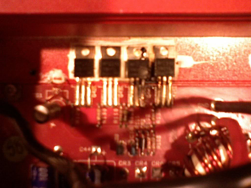
I recently picked up an old MTA 225 amp locally, It was working great for a few weeks and really surprised me. However, the other day it let out it's magic smoke and I discovered a toasty FET. Crappy Pic attached
The blown part is a power supply fet (MTP25N05E) which seems to be discontinued by Motorolla. Looking through these forums I found a direct replacement FET (IRFZ34N) as well as other commonly recomended replacement parts (IRFZ44/IRFZ48) It there a real difference with the different suffixs (N,Z,V) on these FETs?
I was wondering if there were any real advantages to each part choice. I believe I will need to change out the gate resistors if one of the latter 2 parts are used. The current resistors are 470 ohms which is quite a high value for most FETs.
I plan to intially replace all 8 power supply FETs if necessary (they seem to be in 2 groups of 4) along with the gate resistors.
Any insight into parts choices/recomendations is greatly appreciated.
Thanks
After browsing around a bit this forum seems to be a pretty useful site regarding amplifier repairs.
I recently picked up an old MTA 225 amp locally, It was working great for a few weeks and really surprised me. However, the other day it let out it's magic smoke and I discovered a toasty FET. Crappy Pic attached
The blown part is a power supply fet (MTP25N05E) which seems to be discontinued by Motorolla. Looking through these forums I found a direct replacement FET (IRFZ34N) as well as other commonly recomended replacement parts (IRFZ44/IRFZ48) It there a real difference with the different suffixs (N,Z,V) on these FETs?
I was wondering if there were any real advantages to each part choice. I believe I will need to change out the gate resistors if one of the latter 2 parts are used. The current resistors are 470 ohms which is quite a high value for most FETs.
I plan to intially replace all 8 power supply FETs if necessary (they seem to be in 2 groups of 4) along with the gate resistors.
Any insight into parts choices/recomendations is greatly appreciated.
Thanks
That appears to be a clone of an older PPI amp. The 470 ohm resistors should be replaced with 100 ohm resistors if you're going to use the IRFZ44s.
The suffix generally only means that there are minor differences. For power supply applications, it's typically insignificant.
You need to replace all 8 FETs in the supply. You also need to check the output transistors to see if any have failed.
The suffix generally only means that there are minor differences. For power supply applications, it's typically insignificant.
You need to replace all 8 FETs in the supply. You also need to check the output transistors to see if any have failed.
That appears to be a clone of an older PPI amp. The 470 ohm resistors should be replaced with 100 ohm resistors if you're going to use the IRFZ44s.
The suffix generally only means that there are minor differences. For power supply applications, it's typically insignificant.
You need to replace all 8 FETs in the supply. You also need to check the output transistors to see if any have failed.
Yeah I think these amps are similar to the older PPI Pro-mos or something.
I assume I should take the outputs out of the circuit to check them properly?
Thanks for the help, Ive read over your tutorial and it has a lot of great information
OK I pulled all of the PS FETs and their gate resistors, and am waiting for the parts.
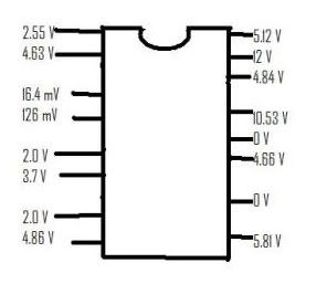
So in the mean time I hooked the amp up to a limited power source to check the IC. DMM neg probe on amp ground, with pos lead touching the IC pins. Below is a beautiful MS Paint drawing of my results. I hope these recorded values are what is to be expected. Any 2nd opinions would be appreciated.
IC is a SG3525A
I didn't see your post from the 8th.
The outputs can generally be tested in the circuit. When they fail they will most commonly be shorted between legs 2 and 3.
The voltages on this IC are approximately what you'd expect to see.
Do pins 11 (4.66v) and 14, (4.84v) go directly (~0 ohms) to the gate resistors?
The outputs can generally be tested in the circuit. When they fail they will most commonly be shorted between legs 2 and 3.
The voltages on this IC are approximately what you'd expect to see.
Do pins 11 (4.66v) and 14, (4.84v) go directly (~0 ohms) to the gate resistors?
I didn't see your post from the 8th.
The outputs can generally be tested in the circuit. When they fail they will most commonly be shorted between legs 2 and 3.
The voltages on this IC are approximately what you'd expect to see.
Do pins 11 (4.66v) and 14, (4.84v) go directly (~0 ohms) to the gate resistors?
Yeah I tested the outputs for shorts in circuit and they all seemed OK.
And yes pins 11 and 14 lead to the two different sets of PS FETs (within ~0.2 ohms) could be within the tolerance of my crappy meter. I also noted ~4.6 volts at the gate resistor pad of the PS when power was applied.
Thanks for all your help
It's likely to be OK when you power it up after replacing the resistors and the FETs but you should have all transistors clamped tightly to the heatsink and have a 10 amp fuse or a current limiting resistor in the B+ line when you apply power.
Yeah I have been testing it out with a 15amp resistor thus far. I will use that or a bulb in series with the B+ when testing it out.
I will put the new parts in next week. Thanks for all your input
I will put the new parts in next week. Thanks for all your input
I replaced the PS fets with the IRFZ44 and changed out the gate resistors to 100ohms. I clamped it into the heatsink and powered it up. It blew the 15 amp fuse quickly. It doesn't blow a 30 amp fuse though. The power light does not come on, It did flash for a second at one point but doesn't stay on.
The PS fets get warm quickly when powered up. ~0.5 Volts is still read at the the pads for the gate resistors.
Any ideas? Thanks
The PS fets get warm quickly when powered up. ~0.5 Volts is still read at the the pads for the gate resistors.
Any ideas? Thanks
None of the outputs read anything close to a short.
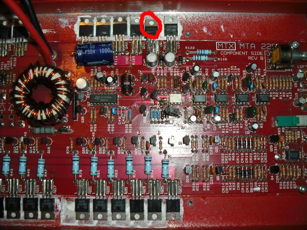
However I did read ~0.7ohms across legs 1 and 2 of a device labeled L7815 CV. This seems to be a regulator.
However I did read ~0.7ohms across legs 1 and 2 of a device labeled L7815 CV. This seems to be a regulator.
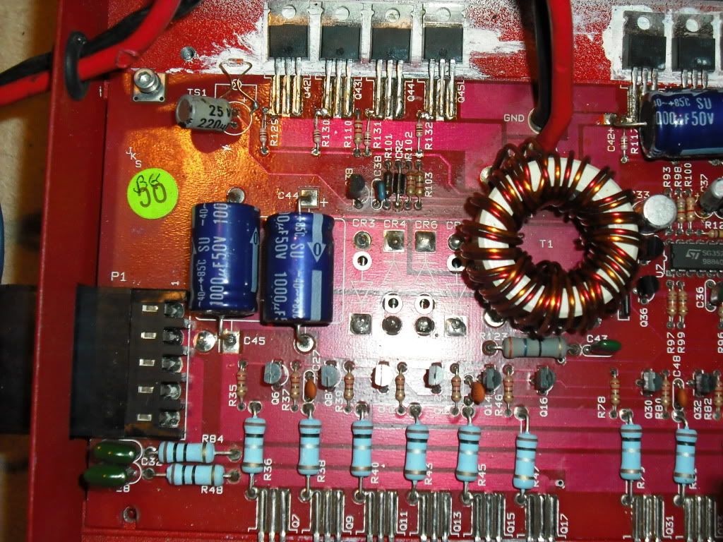
I will be able to post a better pic of the board later tonight, my camera phone isn't cutting it.
Remove the regulator and check it out of the board. 0.7 ohms would definitely mean it's defective.
Remove the regulator and check it out of the board. 0.7 ohms would definitely mean it's defective.
I believe a few weeks ago I actually did pull it out and test is using one of the methods in your tutorial. And it was found to be ok, however I may not trust my memory so I will pull it again.
I don't have any test procedures for regulators online.
Do you read anything near 1 ohm across solder pads 1 and 2 with the regulator out of the circuit?
Do you read anything near 1 ohm across solder pads 1 and 2 with the regulator out of the circuit?
Ok...I pulled the regulator out of the circuit and it is not shorted. Between pads 1 and 2 it still reads 0.7 ohms.
It seems as if leg 2 runs to leg 3 through a capacitor then a diode...I measured the same 0.7 ohms through the capacitor till the first leg of the diode.
It seems as if leg 2 runs to leg 3 through a capacitor then a diode...I measured the same 0.7 ohms through the capacitor till the first leg of the diode.
remove the rectifiers and check them. While they're out of the circuit, re-check the resistance across the cap.
Ok here are the pics of the board. The regulator in question is circled in red (It was desoldered, but I left it in place for viewing purposes). I am unsure where the regulators for this board are located. Are they the large diodes that run on the underside of the board (CR3-7)? Seen beside the large blue caps in pic 1.
- Status
- Not open for further replies.
- Home
- General Interest
- Car Audio
- MTX MTA 225 Repair