Nearly all of us spend our lives searching solutions for an elusive Holy Grail of the amplification, but this time I can say my Holy Grail found!
This is the second time I'm using NP capacitors across DC power supply with excellent sonic results in a DIY amplifier: the first time some years ago in a solid state headphone amplifier, and now in my tube amplifier.
But today is different, since the working voltage is ten times higher than in SS amplifiers. Thus, please take this just as an electronic reading and do not test by yourself (disclaimer): I'm already testing, I'm still alive and my house is not burned yet...
Non-polarized electrolytic caps have the same basic construction as polarized, except they use two anode foils with the electrolyte saturated separator interposed between, rather than an anode and a cathode.
Two normal electrolytic (polarized) 470µF 400V capacitors in series back-to-back (negative-to-negative) will work as a substitute.
Two identical electrolytic back to back capacitors in series halve the total capacitance, but won't give double the voltage. With voltage across the pair, one will act as a cap while the other as a short. Thus our 470µF/400V plus 470µF/400V series returns a 235µF/400V NP capacitor.
It would be best to add diodes across at least the capacitor connected to ground in order to prevent reverse powering as electrolytic caps can withstand some reverse voltage, but not too much. If we apply reverse voltage, the insulating oxide layer un-forms and current flows, the cap heats up and generates gas. Now the only reason for which current can flow in either direction is that the separator is wet, and that wetness dissociates into gas. It's the gas pressure that blows the capacitor. Large ones often have a pressure vent - if they don't, they can explode with some violence. But adding those "safety" diodes made the circuit too much non-linear, and in fact sound gets immediately worse, as it was before adding the back-to-back caps. Thus, after some listening tests, I left the diodes out and, anyway, till now everything is working very quiet without them.
What is important is not so much the duration for which the cap sees reverse voltage across it, but rather the total number of electrons that leak through the cap in the reverse direction: as long as you keep an electrolytic capacitor reverse-biased without drawing much current, all is fine. However, when you have two back-to-back, the forward-biased capacitor prevents a prolonged DC current from flowing. The 160mA fast fuse in the circuit is mandatory, as the forward-biased cap could fail short or increase too much the leakage current in the near future. Usually, as they are new, IL<0.02CV, so in our case is about 3mA, which looks safe to me.
Studies about commercial Bi-polar electrolytic capacitors in audio circuits have proved that any significant DC bias voltage does unbalance a Bi-polar capacitor, resulting in increased second harmonic distortion, free from visible intermodulation and shows no measurable increase in third harmonic: everything is still little more than half a polar capacitor’s distortion measured even when using its optimum DC bias. Unfortunately the same studies proved that back-to-back pair distortion is double that found with the commercial Bi-polar. Special Bi-polar aluminum electrolytic capacitors designed for bipolar DC operation are already available on the market today, and usually referred to as "non-polarized" or "bipolar" types. But the commercial maximum rated voltage available for electrolytic Bi-polar in DC applications is usually only 100VDC and they are very expensive, so the easiest solution here remains the back-to-back pair.
Decades ago Bartolomeo Aloia, an Italian designer pioneer of the Italian High Fidelity, has proved with incontrovertible instrumental documentation that the signal of an audio amplifier passes even through the power cord towards the electric power transmission line. The study in question highlights how the AC audio signal inevitably passes through the power supply circuit including the transformer and the electrolytic filter capacitors, forming a secondary AC audio path. All the current that circulates in the load, circulates likewise verbatim through the entire power supply unit, as if this were in series to the signal. Thus a better AC behaviour of the electrolytic supply capacitors is significant and greatly audible and influences overall sonic performance.
When I say "excellent sonic results" or "sound got immediately worse", is nothing related to a better frequency response or 3D improved soundstage or reduced distortion or lower noise or a better realism: "excellent sonic result" means to me "much less fatiguing listening" as it tends to produce somewhat clearer and smoother, with benefits for ambience as well. This solution is actually my Holy Grail of the amplification, probably partially due to a different distribution of the even harmonics in the signal path, as we could consider the back-to-back capacitors in series with the audio signal, which means that any AC signal would likely pass through them (see pic).
Attachments


Last edited:
Member
Joined 2009
Paid Member
How is this different than anything else if it's just bipolar caps connected to ground? Just a little distortion?
Why do you still have other capacitors in there?
Why do you still have other capacitors in there?
Last edited:
Member
Joined 2009
Paid Member
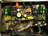
The diagram shows a typical SE amplifier with transformer output. The caps are in the usual places, but they are non-polar electrolytics. I've used NP caps in SS amps and found them very good. Never tried them with tubes though.
Why do you still have other capacitors in there?
The other electrolytic polar capacitor was already in and acts as DC reservoir capacitor after the chocke. I doubt that the back-to-back cap could do this properly. Thus I left it in the circuit. I didn't test without it.
The additional back-to-back NP big size capacitor acts as favourite path of AC signal.
The smaller NP polyester capacitors acts better to bypass HF/RF signals.
Boy, the Brits are in rude-mode today.
That's typical of British Humour 😱
WHAT AC signal? This filter is after the rectifier, so you should have nothing but positive going pulses.
To do science, did you try installing a plain old polar cap in the same position of similar value? In other words your difference might be the increased capacitance, not the bipolarness.
To do science, did you try installing a plain old polar cap in the same position of similar value? In other words your difference might be the increased capacitance, not the bipolarness.
Member
Joined 2009
Paid Member
WHAT AC signal? This filter is after the rectifier, so you should have nothing but positive going pulses.
To do science, did you try installing a plain old polar cap in the same position of similar value? In other words your difference might be the increased capacitance, not the bipolarness.
the signal AC is what flows through the cap after the rectifier. The signal current, like any other, has to flow in a loop. What signal current flows through the tube and output transformer must complete a loop through the power rail decoupling capacitor and cathode capacitor.
a single ended amp like this will be sensitive to the quality of the power supply and the capacitors.
http://diy.ecpaudio.com/2008/03/SSS.html
How about using AC motor run or start caps?
Motor START caps ARE non polarized electrolytics. They provide a temporary phase shift to the start winding, and are removed from the circuit once the motor is up to speed.
Motor RUN caps are in series with one winding on an AC motor continuously. They are directly connected to the AC line (mains) and thus must be tough enough to eat all the surges that the power company throws at them. In Air conditioner use they see about 10 AMPS of constant AC current through the cap. It must have a ultra low ESR and DF or it will explode. They are typically polypropylene in oil.
Stick those in your power supply. We have been doing that on the SSE builds for 8 years. You will get far better transient response and better bass. A 370 VAC cap can eat about 450 VDC.
Thanks tubelab for that enlightening answer..Motor run are better but sometime seller says its motor run even though its a motor start...how can we distinguish it since some look alike?
Grid bias and remove the capacitors
Yes, you will get rid of one minor capacitor, the bypass cathode one, but the secondary AC signal path still would involve the power supply filter ones.
The benefit of NP capacitors is much higher in power supply than in the bypass cathode. I stayed with NP capacitors across the cathode for months, but the magic sonic change occurred only when I installed NP (better, back-to-back) capacitors across DC power supply.
To get rid of this too, you would need a pure inductive power supply filter.
Read this, last page is in english:
http://www.trinaudio.com/webadmin/gestione_catalogo/pdf_prodotti/alimentazione_induttiva_183587891.pdf
Different electrolytic capacitors have different characteristics. There's a reason why you can buy a dozen (at least) different through hole capacitors in popular values from Digi-Key and Mouser. Some have extra high ripple current, some have higher resonance, etc. They are all intended for different applications.
Many non-polar electrolytics are designed for audio applications (like passive speaker crossovers) and although their quality varies widely, the geometry can be optimized (at the expense of other parameters) for lowest distortion in passive crossover circuits. Supposedly other electrolytic capacitors can (like the Nichicon Muse) are optimized for audio too. I can't tell a difference between the Muse and some other capacitors I have (a whole lot of different kinds collected over decades) but I'm old and blind and pretty deaf too. I do have a small stash of various values of Muse capacitors and I am using them up.
Using capacitors correctly is beyond the scope of my discussion, but in the case of crossovers (where the impedance of the capacitor in the circuit is significant) choosing the right capacitors is critical for optimum performance.
In short, I am not surprised that non-polar capacitors offer subtle performance enhancements in power supply and bypass applications. One of the applications I have used the Muse capacitors in with promising results is in bypassing op amps and buffers. I have built a couple of headphone amp circuits with resolution that I have never heard in my life; you can not only hear each instrument very distinctly, but you can hear the mixer tech changing the settings too. This is true even on old digitally remastered mixes that I have listened to for over 40 years (in analog form). And I can't hear sh!! over 12 kHz any more, I guarantee you.
How about using AC motor run or start caps?
I would not use anything electrolytic in DC power supply that in datasheet has "VAC" for the rated voltage parameter. Two examples here.
A part of the initial description, the first are NP which can be used in DC, and in fact rated voltage parameter refers to "VDC"; the second are a Motor ones and any rated voltage parameter refer to "VAC".
DC application (or where the polarity is unknown) :
http://www.mouser.com/ds/2/88/SN-20470.pdf
http://bmicaps.com/wp-content/uploads/2015/05/610d.pdf
AC application Motor Run/Motor Start:
http://www.mouser.com/ds/2/88/PSU-24058.pdf
http://www.elcomp.net/conis.pdf
http://www.kemet.com/Lists/ProductCatalog/Attachments/412/KEM_AC104.pdf
But you will not find anything electrolytic higher than 100VDC with capacitance higher than 100uF for DC application (or where the polarity is unknown)
Last edited:
WIMA?
Ok 🙂, but that is poly, not electrolytic. Have you seen the cost: 240 euro plus VAT plus shipment....not at stock...
DCH3G06250H000KS00 WIMA | Mouser
But I agree with you, if you can afford it that cap could be a real touchable Holy Grail !!
In any case I didn't test poly vs back-to-back electrolytic capacitors: logic says that poly should work much better than back-to-back electrolytic, but as I stated, I suspect that improvement comes from a different distribution of even harmonics, for which only the back-to-back electrolytic would suffer.
Last edited:
- Status
- Not open for further replies.
- Home
- Member Areas
- The Lounge
- My Holy Grail of amplification found: Non-Polar electrolytic caps across power supply