Hi everyone.
This topic I've made to present my way of modification of not expensive, PP class A Audio Institute VR-70E Amplifier, however if there are any Dynavox VR-70E owners, considering / planning any mods as well - both units are the same build, probably comes from the same, Chinese factory. The only difference are:
Audio Institute vendor "Affordable Valve Company" was (perhaps still is) located in UK;
Dynavox vendor "Dynavox" is located in Germany;
Description on schematics & PCB is a bit different - eg. same C7 cap in Audio Institute was C26 in Dynavox as far I remember.
Hope someone like it, as I do. That much, so I found myself some potential to use there. So like the others, who done their steps to improve the sound.
Was it worth it? Absolutely. Worth every penny I spend on it since I bought it 🙂
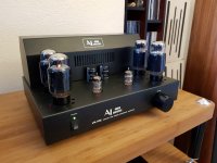
This is the photo on how it was look like on the day of arrival to me. By the way that was also the last photo where it was look like that:
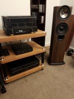
I have to say honestly I am not really keen with all that things. I know how to use soldering iron, or how some elements look like (or should look like while investigating faults), and some of their purposes. I know that the sound will be somehow changed if you use different one instead. That's all.
So I was guided by other Forum guys. Pretty experienced in this things -the Creators, the path finders, audio freaks and inventors - so I was fully trust them in their suggestions.
They also knew about my sound preferences and treat that as a aim in this modding. That's about open, warm sound with not dominating trebles - great micro- and macro dynamics and resolution. Wide and a bit deep scene, nice instruments location.
Their help was look like that - "Solder this one in that place and tell us if you like the change. We know you'll probably do, but we are ready for use alternatives in case of dislike". Quite safe (especially for the wallet) way of fun isn't it? So I tried.
I've done few things, but please allow me to split in more than one post - to make it clearer, and for giving the chance to stay on one job while someone have any questions. I will do my best to answer them fully. There's also good way to do the mods in steps. That helps for easy, quick return to the sound before we discover that sounds disappointing for us.
Starting the job was pretty easy & quick, founded somewhere over the Web, but the improvement was seriously noticeable - removing input capacitors, those ones right after the volume pot - marked on PCB as C0:
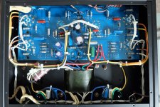
The sound become more open and spacious, also bass became a bit tighter. This small improvement forces me to look for some mods and seek for advice that led me to the guys mentioned above 😉
Stay tuned...
This topic I've made to present my way of modification of not expensive, PP class A Audio Institute VR-70E Amplifier, however if there are any Dynavox VR-70E owners, considering / planning any mods as well - both units are the same build, probably comes from the same, Chinese factory. The only difference are:
Audio Institute vendor "Affordable Valve Company" was (perhaps still is) located in UK;
Dynavox vendor "Dynavox" is located in Germany;
Description on schematics & PCB is a bit different - eg. same C7 cap in Audio Institute was C26 in Dynavox as far I remember.
Hope someone like it, as I do. That much, so I found myself some potential to use there. So like the others, who done their steps to improve the sound.
Was it worth it? Absolutely. Worth every penny I spend on it since I bought it 🙂
This is the photo on how it was look like on the day of arrival to me. By the way that was also the last photo where it was look like that:

I have to say honestly I am not really keen with all that things. I know how to use soldering iron, or how some elements look like (or should look like while investigating faults), and some of their purposes. I know that the sound will be somehow changed if you use different one instead. That's all.
So I was guided by other Forum guys. Pretty experienced in this things -the Creators, the path finders, audio freaks and inventors - so I was fully trust them in their suggestions.
They also knew about my sound preferences and treat that as a aim in this modding. That's about open, warm sound with not dominating trebles - great micro- and macro dynamics and resolution. Wide and a bit deep scene, nice instruments location.
Their help was look like that - "Solder this one in that place and tell us if you like the change. We know you'll probably do, but we are ready for use alternatives in case of dislike". Quite safe (especially for the wallet) way of fun isn't it? So I tried.
I've done few things, but please allow me to split in more than one post - to make it clearer, and for giving the chance to stay on one job while someone have any questions. I will do my best to answer them fully. There's also good way to do the mods in steps. That helps for easy, quick return to the sound before we discover that sounds disappointing for us.
Alright, let's change this Amp... but first:
I know that's may be boring for some people, but read it as somewhere in this text you'll may found something funny 😉
Before you open your Tube Valve Amplifier, you'll have to know that the voltages you may find there are much higher than in your wall socket! Accidental contact will be harmful for you or even cause death. You don't need to discover on yourself that the colour of electric is blue 🙂 Do not make any repairs, or modifications when your unit is plugged to the mains and take extra care in time of making any measurement that requires your Amp to be switched on.
If you willing to make any part of the mods below, please undarstand that I am not taking any responsibility for any failures or damages caused while those mods are undertaken, or after that time...
Starting the job was pretty easy & quick, founded somewhere over the Web, but the improvement was seriously noticeable - removing input capacitors, those ones right after the volume pot - marked on PCB as C0:

The sound become more open and spacious, also bass became a bit tighter. This small improvement forces me to look for some mods and seek for advice that led me to the guys mentioned above 😉
Stay tuned...
Here we go again 🙂
Sorry for a bit delay, being busy at the moment.
After small, first step (removing input Caps) I was advised to do some changes in power supply.
Replace 2x 470uF 250V Capacitors with 2x Kemet 680uF 250V. Those Caps actually are seen behind 6NF2 Valves. Kemet Caps are bigger - fortunately in length. As they coming out through the top they doesn't obstruct with anything else.
On the photo below you can see how they look - old caps are half size of them:
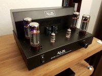
70V circuit - adding parallel Mundorf MCap Supreme 0.1uF 1400V next to C24 & C25 220uF 100V caps factory fitted there.
More changes in 420V circuit.
Stock Rectifier Diodes replaced with extremely fast switching Wolfspeed Z-Rec 1.2 kV, 10 A, 11 nC Diodes.
Both helping guys foud that B+ wires are soldered on PCB in the worsest possible place. Right after their suggestions both wires been soldered to positive pole of C21 Cap.
C8 0.47uF 350V Filter Capacitor residing there been replaced with Mundorf MCap MKP 1uF 630V + parallel Mundorf MCap Supreme 0.1uF 1400V
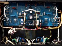
Quick thoughts after power supply changes. Sound became yet more open & airy. Also been better detailed with much less distortion. Smooth. Nicely smooth 🙂
The Amplifier having now quite better ability to drive speakers, bass kick became faster, punctual and more accurate. Faster beats became more recognisable in music, lower frequencies just gets more pleasant.
Soon after those changes I've get rid of negative feedback Caps (C5 on PCB) and used Charcroft Audio Silver Mica 47pF 500V Caps. Funny fact I've discovered there - description on PCB say that there supposed to be 100pF Caps, however I found 220pF in one channel and 47pF in the other. So what was top frequency limit so far? God knows... Can't actually remember what changes in sound I've had after that change, definitely was something to do with resolution. Charcroft Audio Silver Mica had opinion of the best to use in negative section anyway - worth any penny there 🙂
More to come...
Sorry for a bit delay, being busy at the moment.
After small, first step (removing input Caps) I was advised to do some changes in power supply.
Replace 2x 470uF 250V Capacitors with 2x Kemet 680uF 250V. Those Caps actually are seen behind 6NF2 Valves. Kemet Caps are bigger - fortunately in length. As they coming out through the top they doesn't obstruct with anything else.
On the photo below you can see how they look - old caps are half size of them:

70V circuit - adding parallel Mundorf MCap Supreme 0.1uF 1400V next to C24 & C25 220uF 100V caps factory fitted there.
More changes in 420V circuit.
Stock Rectifier Diodes replaced with extremely fast switching Wolfspeed Z-Rec 1.2 kV, 10 A, 11 nC Diodes.
Both helping guys foud that B+ wires are soldered on PCB in the worsest possible place. Right after their suggestions both wires been soldered to positive pole of C21 Cap.
C8 0.47uF 350V Filter Capacitor residing there been replaced with Mundorf MCap MKP 1uF 630V + parallel Mundorf MCap Supreme 0.1uF 1400V

Quick thoughts after power supply changes. Sound became yet more open & airy. Also been better detailed with much less distortion. Smooth. Nicely smooth 🙂
The Amplifier having now quite better ability to drive speakers, bass kick became faster, punctual and more accurate. Faster beats became more recognisable in music, lower frequencies just gets more pleasant.
Soon after those changes I've get rid of negative feedback Caps (C5 on PCB) and used Charcroft Audio Silver Mica 47pF 500V Caps. Funny fact I've discovered there - description on PCB say that there supposed to be 100pF Caps, however I found 220pF in one channel and 47pF in the other. So what was top frequency limit so far? God knows... Can't actually remember what changes in sound I've had after that change, definitely was something to do with resolution. Charcroft Audio Silver Mica had opinion of the best to use in negative section anyway - worth any penny there 🙂
More to come...
Last edited:
Just the reminder - VR-70E works in Ultra Linear 2x40W mode by default. The vendor - Affordable Valve Company was offering this mod for £158 stating "YOU CANNOT GET FAIRER THAN THAT !". Seriously? Overall cost of Triode setting starts from few Pennies to few Pounds if we decide to have it switchable version. The output power in Triode mode is 2x20W.
Somewhere in the meantime I tried this Amp in Triode mode. Experienced DIY-ers surely know how to do it, however I will show the example on my unit if any owners are interested.
Job is simple - need to disconnect, isolate and leave away four wires marked on both channels as SG1 for bottom Valves and SG2 for the top ones. Solder small bridge between P1-Sg1 and P2-Sg2 on PCB for both channels. Job done, photo below - you can see small bridge wires in clear sleeves there:
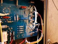
Some people prefer Triode mode, some others stay with UL. Can't decided? You can always implement switches - they can be found factory fitted in some other brand Amps 😉
Somewhere in the meantime I tried this Amp in Triode mode. Experienced DIY-ers surely know how to do it, however I will show the example on my unit if any owners are interested.
Job is simple - need to disconnect, isolate and leave away four wires marked on both channels as SG1 for bottom Valves and SG2 for the top ones. Solder small bridge between P1-Sg1 and P2-Sg2 on PCB for both channels. Job done, photo below - you can see small bridge wires in clear sleeves there:

Some people prefer Triode mode, some others stay with UL. Can't decided? You can always implement switches - they can be found factory fitted in some other brand Amps 😉
Interesting mods that I'm keen to try out. I particularly like the simpler component mods, but I'd also like to install a DPDT switch to move between UL and triode mode at will. I'll do the simpler mods first. By the way, something with the resoluton or scale of your pictures causes my browsers to flip a bit; not sure if anyone else is having that problem too? Anyway, as you know, I also have this amp and I've turned down the tube bias to ~350mV as suggested. I've noticed a couple of posts elsewhere giving the bias at <300mV (250-270mV; too low in my opinion)! Having a small listening room, I've got my amp connected up to a pair of 27 year old Mission 780s (the original Cyrus version from c1990). These old speakers still sound good and connected to my relatively unmodified (the input and power supply caps have also been upgraded), they sound excellent! Far better than a pair of contemporary Wharfedale 10.1s I compared them with a few weeks ago. It's a surprisingly dynamic amp isn't it!?
I am spotting that problem with photo from time to time - entering this topic, or some others. Hit Ctrl+F5 for decent refresh resolving it for a few days 🙂
It is happen in the Forums, where script opens the photos from hosting used by me in new window - instead of new tab.
Setting bias lower than desired (350mV - reminding) will result in cold sound. Not that we expect from Tube Valve Amps - isn't it 🙂
I am running this beauty made in 2007 with 15yo speakers (Sonus Faber Grand Piano Home), and for now I don't want anything newer than that!
Yep, micro & macro dynamics is pretty good with stock parts - however mods I've done in power supply areas just change that for even better. Way better 😉
Now some bad news - something what stops me from carry on this topic for a bit, but will be carried forward pretty soon.
Anyway, my amplifier has decided to have some rest last Thursday and give up in right channel. One not loud bang comes in speaker and constant low freq. hum after. First thing get to my head - check bias - in case if one of the Valves failed.
Check the Tube next to transformer in right channel - bias OK.
Do the same with the Tube on front - 2000mV scale has gone! Turn on 20V scale and nearly collapse myself - just over 18V of Bias!!! Tried to turn it down, no result. Swap Tubes in places - no change, still the same circuit. Grab the screwdriver again and turn clockwise few times to see if go lower. Finally gone down, however Bias stays very unstable, builds up after turning on very slowly and what worse hum still was audible from the speaker. Apart from that the sound remains undistorted etc.
Turn it off again (still with Multimeter connected to the test point) and another weird symptom spotted - Bias voltage instead of disappear has double up in seconds and starts slowly dropping down. That takes almost three minutes to disappear...
I've made the video of that: YouTube you can hear that hum just before I've turned Amplifier off and see what's happen after with Bias.
Next day I've open it and start tracing the fault. All inside was looking alright, so I grab the Soldering Iron and Multimeter and start chasing the problem by de-soldering and measure values of resistors in the circuits of faulty section on PCB. Got ya! The 10 Ohm Resistor found as down. Unfortunately it will take few days to parcel arrive - I will change all 10 Ohm & 200 Ohm Resistors (originally should be 100 Ohm, but I will leave current values). So I am making some more small mods, which will be added to this topic after 🙂
mintymiller, don't be afraid to try mods there - it is simple as both: soldering and components are on the same side of PCB (except of biggest snap-in Caps, however still easy to go on with). Cannot imagine easier try-out option for non advanced users of the Soldering Iron 😀
Some people recommend to use paper-in-oil caps, but I've been told to stay away from them, as the cheaper Mundorf Supreme & ZN Caps will do "easy, non extravagance & decent job instead". Can't argue with that matter of affordability - simple as it is 😉
Some people recommend to use paper-in-oil caps, but I've been told to stay away from them, as the cheaper Mundorf Supreme & ZN Caps will do "easy, non extravagance & decent job instead". Can't argue with that matter of affordability - simple as it is 😉
I am spotting that problem with photo from time to time - entering this topic.... 🙂
Please use the Attach function on this forum.
1) the image will stay with the thread even if the external host goes off-line (or greedy like PhotoBucket).
2) the forum has the image and will RE-SIZE it to fit in my browser window: it won't spill off the monitor, off the desk, and startle my sleeping dog. (Or give the browser a fit.)
Attachments
Last edited:
Thank you. But I would love to keep all my photos on my hosting site, which they wouldn't never disappear. I am actually keeping there all my photos shared on every Forums I am writing since 2002 year. There is not even one that gone away after all that years 😉
www.fotosik.pl is the one of the most stable hosting sites, fortunately very trouble free 🙂
The issue only happens on modified vBulletin scripts (they have problems with real-time photo resize sometimes). Not tend to be happen on genuine vBulletin script, as it is used by some Forums I am the citizen 😉
As ex-Admin of some Forums I am up to place photos on hosting sites - instead of use Forum's server space. Sorry it is in my DNA and I can't help it 😀
Last edited:
The next step was replacing coupling capacitors with Mundorf MKP ZN Caps - which I really can't remember now what progress they made. But I remember they works - so that you can be sure. No waste of money definitely.
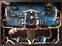
But I remember change original potentiometer for stepped attenuator and not really enjoyed that part...
Why? Not many attenuators have compact size to fit the space of ori pot in its place. This one (you also can see on the photo above) does barely fit there, but the quality (unfortunately reflect the price) is away from what anyone could expect.
After first assembly one channel doesn't run at all, I had to disassembly "on pieces" and find out the reason. First look - it's silver plated - and very able to "wear & tear" there. Adjusting the connections and put back, trying again.
OK, both channels running, but one of them significantly quieter than other. Enough for me, not wanted at all, put the old one back and look for something else instead.
I think even the Chinese seller knows what crap they are as when I was requested the return he told me to keep it while he gave me money back... That's explains everything about this one for me...
Must say I was really enjoyed stepped way of the original Pot.
After Stepped Attenuator episode I bought stepped version of Alps "Blue Beauty" - 100KAX2. Guys what is "beauty" in this thing? Black Alps was outstanding, no doubt one of the best in quality - price relation potentiometer on the planet. But blue?
Firstly - I tried three (two stepped, one stepless) and channel balance on the lowest settings been always put in question.
Secondly - the midrange, vocals been dry and without emotions - really I want to say: were soulless.
Whoever put this inside of his device must really consider something with only a bit more cost - Audio Note Potentiometer. I've grab AN-100K. Not stepped, but I can forgive that. Why? because in this price range (currently £31.68 at hfc), it is far, far beyond of that you won't find - no competition for this one there. Simply I loved it!
Found the opinion it is a lot better from basic TKD model 2CP-601 and very similar to TKD 2CP-2511 for almost three times more - but I am not judging 😉
Try if you dare, put your observations here in this topic.
Hi fella's (and gals....)
Hi Tomekkk1 and anybody else reading
I just picked up one of these amps in the Dynavox flavour. I pick it up tomorrow night. No EL34's at mo but I'm gonna get a quad of KT77's for it. Been good reading your posts so far matey, looking forward to see the rest of you're mods.
I planning to get rid of the input and phase splitter as I have an Aikido Preamp built so I'm using that for voltage gain and then going to convert the triode/pentode into a diff pair for phase splitting.
I'm definitely changing those 10 Ohms thou ! just in case ....
looking at your pic's it seems that the grid stopper resistors are not connected properly they should be between 0.47uF caps and the EL's grids, at the mo the caps run the signal straight into the grid and the 100k Ohm resistors are doing nothing to stop any oscillation.
gotta stop now .... out of breath
James
Cheers mate!
So you got a plan and proper aim - good luck James!
Good job that resistor failure doesn't drag any consequences to the Valve. I think so, as I was swap two of them in places to verify the side of the fail - valve side or Amp side. No idea if Tube Valve lifespan was affected or not, but I am not to worry up front for that reason.
At least I know few facts now - the Amplifier is a bit over ten years old, so simple bits have right to give up their lives there. And resistors replacement for a bit better than stock ones is not drilling wallet much - so it is a good time to refreshment 😉
I am not very keen with electronics, so location of that 100k Resistor is "as it was" - as I don't now much about it. Simply no idea why someone designed that circuit that way and what pros & cons could be spotted there - if it will be like you mentioned.
Anyway, it is up and running and I am enjoying music again. So let's carry on the story 🙂
Next step in modifications was testing some Chinese no name Potentiometer - which supposed to be "based on black Alps" basing on seller recommendation. Whole story is worth only four words - terrible quality, horrible sound. In that time I was waiting for delivery of AN-100K from Audio Note, mentioned couple posts ago - so i just tried it in the mean time as I was curious of it.
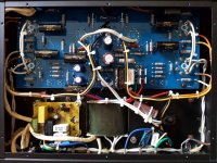
Bigger improvement in that time was adding softstart Circuit. Some people say that is nonsense and may causing problems. This one is well designed with protection at 95°C/6,3A, adjustable time 4-12sec. This is not one of those been sold on eBay by the way.
Fitting this softstart board forced me to reorganise some components in that area - goes quite well, only trouble is that the speaker transformers had to be unscrewed to release rectifier module fitted with one screw and place it by the other side of power transformer.

Last edited:
The photo below was taken after last mods been made up - until Amp broke down. That was while ago - some other was planned, but never made up till I had to re-open week ago. But about those changes will tell you later, let's come back to those changes from the picture.
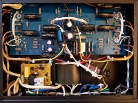
First change - swapped C1 Caps next to 6F2 (ECF82) sockets. A lot better sounding, better in every aspect. That only confirms how crap those original Capacitors are - every change is the winner!
Second one - AN-100K Potentiometer finally sat there, this change forced me to buy new volume knob. Nice big, heavy piece of metal. Simply beautiful, just take a look guys 🙂
Due to "squeezy" resizing of Forum Script I recommend to click on the photos. It will be also better to see changes I was mentioned 😉

First change - swapped C1 Caps next to 6F2 (ECF82) sockets. A lot better sounding, better in every aspect. That only confirms how crap those original Capacitors are - every change is the winner!
Second one - AN-100K Potentiometer finally sat there, this change forced me to buy new volume knob. Nice big, heavy piece of metal. Simply beautiful, just take a look guys 🙂

Due to "squeezy" resizing of Forum Script I recommend to click on the photos. It will be also better to see changes I was mentioned 😉
Hi Tomekkk1 and anybody else reading
I just picked up one of these amps in the Dynavox flavour. I pick it up tomorrow night. No EL34's at mo but I'm gonna get a quad of KT77's for it. Been good reading your posts so far matey, looking forward to see the rest of you're mods.
James
Hi James; yes, there were two of the amps on eBay last week from the same seller; one with and one without valves (modded for no input pot). You must have bought the latter! Good luck with it mate!
The photo below was taken after last mods been made up - until Amp broke down. <snip>
Glad you managed to fix it! I'm still puzzled by the bias settings though. With voltage set to 350mV, my meter shows ~20mA at the test points. I wonder if the calculated supply current needs to be halved in a push-pull configuration? Seems unlikely but it would explain the discrepancy. As you know, I calculated the current based on the valves running at 70% of their max output (so ~17W for 34W/channel). 17/420 =40.4mA which is almost exactly double the 20mA I measure at each test point. I must admit that I don't understand the difference between idle and bias current/voltage. Anyway, my amp sounds really good, particularly on less complex, more acoustic tracks. It seems to get a bit more confused with complex music, but I think that's just as likely to be the source (Spotify 320kbps) or the speakers as the amp and it doesn't bother me that much anyway.
James, according to the schematic for this amp, the resistors are connected between the 0.47µF caps and the grids (G1/G2) but not in series. There is supposed to be an error
Saw a report on the other thread about an error either on the schematic or the circuit board; wonder if this has anything to do with your comment?
I already have three different schematics and any of them is not 100% accurate. Even the closest one have also different parts coding e.g. "C" for Caps have different numbers on the board and schematics. Some values seem to be different as well. 100 Ohm Resistors that's actually 200 Ohm factory fitted in Amp, I've figure that out during fault tracing.
Hi guys
Minty you're right - it was one of those on eBay.
I picked it up last night and was supervised about the build quality, nice chassis.
I'll post some pic's tomorrow. It's already modified a bit some good some bad.
Tom i've scanned the schematic I got with it and posted it below, to add to your collection 😱 Hopefully they go alright I've never attached anything here on Diy.
As for Grid Stopper resistors heres a quick run down if you don't know what they do, sorry if you do - there is a small unseen capacitance between the plates of all valves. It's called "Miller" capacitance. This can cause the amp to oscillate at a very high frequency beyond hearing, this ain't good for anything and can break things. The grid stopper resistors form a 1st order RC filter with this capacitance to stop the oscillation.
They were added on the uprated schematic that I have but my amp is the first version and doesn't have them....yet!. It seems they should be about about 1k Ohm for the El34's.
James
Attachments
- Home
- Amplifiers
- Tubes / Valves
- My mods of Audio Institute VR-70E
