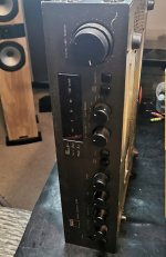
So after the real success of doing the 3020 and 3130 ive decided to do the 3140
You dont see these about much these days-i dont thnk as many were made like the other 2
Few different challenges on this one, particularly the sighting of the FETS-Ii might need a different heatsink, we will have to see
So part one is the dismantle and check it over- and this is what i do to all of my amps as a standard proceedure
someone kindly glued the knobs on-a little bit of gentle heat and they are all off
the spindles will get cleaned and buffed up before they go back on
all screws will be removed and resprayed
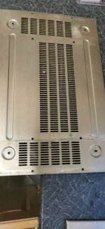
cover and base plate are cleaned with Mr muscle(i find this the best and least agressive) then they will be stored away
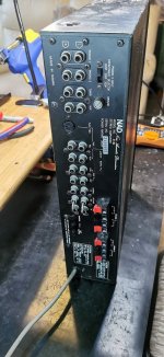
looks like someone kindly recapped this before i brought it, that was good of them wasnt it
Whats left is cleaned in 3 stages
first it is hoovered out, then blasted with compressed air to get rid of any dust
then i clean with 2 different cleaners-holts electrical contact cleaner, then AAB contact cleaner, this leaves a nice finish
Next step once all is dry will be to check the amp over to make sure there are no nasty suprises or faults before i start the conversion
You dont see these about much these days-i dont thnk as many were made like the other 2
Few different challenges on this one, particularly the sighting of the FETS-Ii might need a different heatsink, we will have to see
So part one is the dismantle and check it over- and this is what i do to all of my amps as a standard proceedure
someone kindly glued the knobs on-a little bit of gentle heat and they are all off
the spindles will get cleaned and buffed up before they go back on
all screws will be removed and resprayed
cover and base plate are cleaned with Mr muscle(i find this the best and least agressive) then they will be stored away
looks like someone kindly recapped this before i brought it, that was good of them wasnt it
Whats left is cleaned in 3 stages
first it is hoovered out, then blasted with compressed air to get rid of any dust
then i clean with 2 different cleaners-holts electrical contact cleaner, then AAB contact cleaner, this leaves a nice finish
Next step once all is dry will be to check the amp over to make sure there are no nasty suprises or faults before i start the conversion
Attachments
-
 IMG_20230317_071658.jpg117.5 KB · Views: 254
 -
 IMG_20230317_080627.jpg146.9 KB · Views: 254
 -
 IMG_20230317_080116.jpg124 KB · Views: 235
 -
 IMG_20230317_080108.jpg348.2 KB · Views: 214
 -
 IMG_20230317_080103.jpg222.8 KB · Views: 214
 -
 IMG_20230317_080039.jpg191.3 KB · Views: 220
 -
 IMG_20230317_080035.jpg309.2 KB · Views: 296
 -
 IMG_20230317_074751.jpg579.7 KB · Views: 265
 -
 IMG_20230317_073512.jpg296.9 KB · Views: 249
 -
 IMG_20230317_073456.jpg227.1 KB · Views: 262
 -
 IMG_20230317_072924.jpg404.6 KB · Views: 283
 -
 IMG_20230317_072522.jpg420.5 KB · Views: 284
 -
 IMG_20230317_071754.jpg159.9 KB · Views: 248
 -
 IMG_20230317_071709.jpg158.4 KB · Views: 256

What is the advantage to converting it to LatFETs? I'm a fan of laterals and use them for my own amps, but I am intrigued as to what the advantages would be to convert an existing design, assuming that its thermal tracking works and it functions as intended?
Well the other 2 I have done def sound better, well they do to me and I've listened to loads of these over the last couple of years


I need to increase the bias though as I'm only running it at 10mv at the moment. It was getting to hot at even 30
The heat generation should be identical with the FET's vs the original transistors for a given bias current. If you suspect its running to hot then put the scope on the output and make sure there is no HF oscillation present.
I did scope it and we were all nice flat linesDC nothing g on AC. The bias is only 7mv on the BJT, but is the enough for the FETS
Are you comparing like for like?
What was the resistor value you were measuring across to get 7mv for the BJT and is it the same value resistor you are using for the FET's.
The BJT 3140 uses 0.22 ohm emitter resistors as I recall but for the FET's we don't those and they are better linked out.
What was the resistor value you were measuring across to get 7mv for the BJT and is it the same value resistor you are using for the FET's.
The BJT 3140 uses 0.22 ohm emitter resistors as I recall but for the FET's we don't those and they are better linked out.
So 7mv across 0.22 is just over 30 milliamps. That's a bit on the low side tbh.
100ma is often considered an optimal point but you can go lower than that. As long as the bias current stays put it is OK but the negative tempco of laterals means the bias current can actually fall as they heat and you don't want to end up severely under biased.
100ma is often considered an optimal point but you can go lower than that. As long as the bias current stays put it is OK but the negative tempco of laterals means the bias current can actually fall as they heat and you don't want to end up severely under biased.
Hitachi themselves used 200mA for their own amps (they definitely did for the first, the HMA-7500 - and I suspect it was similar on the others, or maybe higher for the 9500 with its larger heatsinks - I haven't found a complete SM for the 9500). I found out when I started building the Maplin derivatives in the '80s that the suggested 50mA did not give great THD performance, as it's very much a Class B scenario, but in a basic amp whose only real weapon against distortion is bias. Hitachi's apps data suggests 100mA. Lateral FETs just eat bias. You can use dummy load and distortion analyser to find a sweet spot for your application. My Exicons have run at 65-degrees C since 2000.
Hitachi knew that the FETs were happy to run at high temperatures, so in the 7500, the mechanical design was implemented in a way that the end user wasn't exposed to anything hot. The heatsink has a 'shield' made of fibre-board (this stopped debris getting onto the heatsink and internals, as well as funneling heat to the sides). The heatsink also has clearance from the vented lid. With 200mA bias, it was into Class A for a good couple of Watts, but they engineered it to have the appearance of a normal amp.
Hitachi knew that the FETs were happy to run at high temperatures, so in the 7500, the mechanical design was implemented in a way that the end user wasn't exposed to anything hot. The heatsink has a 'shield' made of fibre-board (this stopped debris getting onto the heatsink and internals, as well as funneling heat to the sides). The heatsink also has clearance from the vented lid. With 200mA bias, it was into Class A for a good couple of Watts, but they engineered it to have the appearance of a normal amp.
The heatsink is actually pretty reasonable in size and dispersion is real good so I'm going to increase the bias tomorrow and see what happens. I haven't finished with it yet as I'm going to remove the drivers and VBE next as I did on the others 👍
- Home
- Amplifiers
- Solid State
- NAD 3140 Conversion to lateral FETS