Hello to all, I recently bought a C325BEE unit in full working order, but I was very disappointed with the midrange resolution and finesse.
It seems really strange to me, as I often read about complaints on the treble range, not in the middle.
I want to try a quasi-complete recap of the signal path, mica or polystirene capacitors instead of ceramic ones, new electrolytics (I like cerafine or Nichicon Muse) or substitution with polyester equal values and so on, if anyone is already experienced about this please can suggest something specific to me?
Anyway, having a look at the schematics sincerely I haven't understand what the rc cells R621 and C611 (see schematic attached) is useful to. It connect the two negative input of the stereo line amplifier.
I already seen this kind of topology (with bigger capacitor value) in a differential line amplifier based on two sections that works with balanced input signal. The RC constant of this RC cell suggest that it works form near-RF on (around 3,5 MHz), but:
It seems to me that it has nothing to do with stability, I'm just asking myself if it's necessary all at all, and sincerely I'd need a suggestion about it because I'm not a technician.
Just to give an element to think about, this RC cells disappear in the C326BEE schematics.
Thank you to all
It seems really strange to me, as I often read about complaints on the treble range, not in the middle.
I want to try a quasi-complete recap of the signal path, mica or polystirene capacitors instead of ceramic ones, new electrolytics (I like cerafine or Nichicon Muse) or substitution with polyester equal values and so on, if anyone is already experienced about this please can suggest something specific to me?
Anyway, having a look at the schematics sincerely I haven't understand what the rc cells R621 and C611 (see schematic attached) is useful to. It connect the two negative input of the stereo line amplifier.
I already seen this kind of topology (with bigger capacitor value) in a differential line amplifier based on two sections that works with balanced input signal. The RC constant of this RC cell suggest that it works form near-RF on (around 3,5 MHz), but:
- one has to be sure that both L & R cables are affected by the same type and amount of signal noise to cancel it as a common mode signal
- in the worst case, noise from one channel is injected to the other channel out of phase
It seems to me that it has nothing to do with stability, I'm just asking myself if it's necessary all at all, and sincerely I'd need a suggestion about it because I'm not a technician.
Just to give an element to think about, this RC cells disappear in the C326BEE schematics.
Thank you to all
Attachments

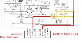
The RC connection is in the C326BEE also: (IN module = 4.7K + 10pf) (OUT module = 4.7K + 94pf (two 47pf in parallel).
Not 100% sure either of the main purpose of the RC network other than to present a common noise floor (reference) between the 2 channels.
I have a C325BEE (parts-only-ebay-special) that I overhauled. It really sounds nice, especially at moderate to high volumes. But at lower volumes I have to adjust tone for more low end response.
But, yes, I really like this NAD.
Hello jhjove,
thank you for your answer, yes, you're absolutely right, the RC cell is present in the C326BEE, too. Sorry, I've searched it in the wrong place.
Well, I've just started to overhaul mine, I hope I won't make damages.. I started with the preamp module, I definitively don't like the ceramic capacitors I've found on it, they seem very cheap parts. Maybe I'm wrong, but surely silver mica ones can't work worst.
Let's have fun!!
Anyway, sincerely I can't manage to understand the function of C213 (470pF to ground) in the out module of C326BEE, seems like it make the two channels works different, isn't it? bah, too low technical skill 🙁
Anyway, sincerely I can't manage to understand the function of C213 (470pF to ground) in the out module of C326BEE, seems like it make the two channels works different, isn't it? bah, too low technical skill 🙁
C213 is bypassing high frequency noise to ground. And being that the node is connected to the L- and R- network, makes sense trying to eliminate as much noise from this node as possible.
I look at these caps+resistors like the RC snubbers that are used to quiet the switching noise from power supply rectifier diodes. The C325BEE uses only 10pf caps across the secondary connections to the diode bridge for both that normal and high power supplies. Still it's a LC network (coil of secondary and cap) working to reduce HF / EMI noise.
For my C325BEE, I didn't have issues with these 2 pre-amp riser PCBs.
I did have to work on the driver riser PCBs though. These had SMD electrolytic caps that were acting more like resistors than capacitors. I had to remove both of the driver PCBs assemblies then carefully remove and replace the SMDs caps.
And instead of standard electrolytic I used solid-polymer-electrolytic SMD replacements with the temp rated at 105C.
-Joe
"C213 is bypassing high frequency noise to ground. And being that the node is connected to the L- and R- network, makes sense trying to eliminate as much noise from this node as possible." yes, it's true, but -Left channel goes to C213 through 4K7 resistor, -Right channel through 94 pF, doesn't this lead to a different behavior between the two channels?
Anyway, I'll try to lower the C value in the C325BEE cell, I've made another mistake (I read a wrong resistor value) and the constant is quite near the audio band, especially the 30K/75pF one. the C326BEE has a very higher time constant due to the R value, appoximatively 1/6, I don't like the idea of audio frequency injected out of phase between the two channels.
Please let me know how will proceed with the SMD capacitors replace!
cheers,
Massimo
Both R- and L- are "seeing" the same structure (see attached image).but -Left channel goes to C213 through 4K7 resistor, -Right channel through 94 pF, doesn't this lead to a different behavior between the two channels?
So you've never "played" with SMD components?Anyway, I'll try to lower the C value in the C325BEE cell, I've made another mistake (I read a wrong resistor value) and the constant is quite near the audio band, especially the 30K/75pF one. the C326BEE has a very higher time constant due to the R value, appoximatively 1/6, I don't like the idea of audio frequency injected out of phase between the two channels.
Please let me know how will proceed with the SMD capacitors replace!
cheers,
Massimo

I've done it infrequently, but successfully. It requires clean solder pads and patience.
If you need to replace the SMD caps on CB11 + CB21 PCBs then it's best to remove the PCBs from the main board. They are pin-soldered to the board....including the metal shield/shroud.
For SMD caps R+R, this youtube video really helped me. It was a repair to a Bose wave radio that required some SMD caps being replaced.
Basically, after brute force removal of the part, I clean the solder pads with solder wick (copper braid) to clear off any loose leads and remove the old solder. Then I add a very small dab of solder paste/flux to the pads. Holding the replacement centered over the area, just touch the exposed leads with the iron and it's done. It's actually quick once you get the hang of it.
--Joe
Attachments
- Home
- Amplifiers
- Solid State
- NAD C325BEE preamp section