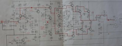
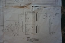
Does anyone have a link to Nakamichi PA-1 schematics or have one in a pdf file? I'm afraid to pay to download any nak manuals because I've got bitten a couple of times by companies that sent download Nak service manuals on items during that time period without schematics. I was unable to get a refund on both occasions. Thanks for any replies
Bumping up..
Does anyone have the service manual or schematic for the Nakamichi PA-1? There seems to be absolutely no material on the internet regarding this unit, not even the user manual.
Attaching the spec sheet from hard copy for anyone wondering what the rating is for this unit:
Does anyone have the service manual or schematic for the Nakamichi PA-1? There seems to be absolutely no material on the internet regarding this unit, not even the user manual.
Attaching the spec sheet from hard copy for anyone wondering what the rating is for this unit:
Attachments
I ended up having to buy it in paper form. Schematics are huge fold out type. Way too big to scan. I could take pics of portions of it if you know what section problem is in.
I have a Nakamichi PA1 All chs sine waves are perfect. When I put a load on any ch the sine wave disappears. Doe anyone have any suggestions?
Thank you.
Thank you.
Are you testing on an oscilloscope? What is the source of the sine ease input? Is it amplified on the output? Could you be reading stray 60Hz?
Tek Signal generator and tek scope, all 5 sine waves are 100 percent clean and stable. All ground seem to be in place. I have repaired over 8000 amps. This one is a puzzle. Sine wave instantly drops to zero whether i connect a speaker or a dummy load
I am checking for an open ground on somewhere.
Thanks for the quick reply.
I am checking for an open ground on somewhere.
Thanks for the quick reply.
Earth loop or short circuit in the measurement circuit (ground generator, amplifier and oscilloscope).
I am a bit puzzled too. The amp is basically a 2 + 3 channel design with separate xformer/rectifier/filter for each section. Are the dc rails’ voltages stable once you put on load?
If you look at that schematic from post #4 there's a capacitor across the protection relay, which explains it - the protection or relay is not activating and only the capacitor is carrying the signal through. Doesn't explain why the protection is operating though.
Yes. I dont have a schematic. There is no power to the relays and the sine wave is passing through the cap.
Thanks MT,
Thanks MT,
GTO 127, Can you please post the relay circuit section, There is no power to the relays.
Thanks a million.
Thanks a million.
About only problem I ever had with mine was due to small cracks in circuit board due to the board not having very good support. Not sure if yours has simuliar problem but thought I'd mention it.
i was wondering if this amplifier's low impedance load handling can be improved by adding output stage BJT pairs assuming psu is capable enough? does anyone have experience in such a mod?
I just got a large scanner so thought Id upload parts of the schematic in pdf format so everyone would have the whole thing. I don't know how to stitch together so it will be in 4 pages,. Sorry about quality. This schematic is coming apart. I didnt realize it when making but you have to rotate each pages 3 times to get correct perspective. I had thought they were saved after I had previously rotated.-I'm not very good with this stuff.
Attachments
- Home
- Amplifiers
- Solid State
- Nakamichi PA-1 Schematics


