Hello everyone,
I am getting into tubes, I am in the process of building a 300B based on a PCB (wich will be easy)
In the meanwhile, waiting for all my coponents to arrive, I baught a LAOCHEN EL34 amp for testing.
It is based on this diagram

The thing is that the sound is really too harsch. I tried tube rolling (tung sol EL34+6SN7GT, PSVANE 5U4G), changing 2 coupling caps with mundorf but I think the schematic is just not good.
Nos I have thransformers and valves on my hands. I thought about rewireing the whole thing but I can't find any schematic usung these 3 types of tubes.
Can anyone direct me in the right direction and provide me a good diagram?
the input transformer is 320V.
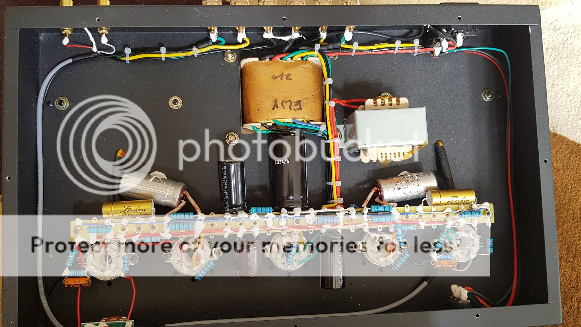
Your schematic, and the pictures of the Laochen EL34 amplifier I've found, seems to be almost identical to the Oldchen/Gemtune BL02 amplifier I have. I attach a picture of the inside, does it resemble yours? Are the voltages on your schematic actual measurements on your amplifier? I plan to rebuild my amplifier due to the obvious issues on sound quality. I tried some alterations to the bias point of both tubes with no appreciable results. This tube complement is common on current China production, and many amplifiers have a different voltage gain stage. I attach a sample schematic of this alternate configuration. I haven't tried it yet, because I am unsure if the input stage is the culprit here. By previous experience, it may be more likely that the small output transformer has been designed for 6V6 - 6P1 and then shoe horned on this EL34 design to meet the low price point. My next planned move is to remove the output transformer and temporarily transplant it on a known good single ended EL34 amplifier I have on the bench now (same 3.5k primary impedence), to check if the issue does moves with the transformer. I wonder if there is a faster way to check if the output transformer is overloaded.
Attachments


yes it seems to be the same amp. I went for the luxury version so some caps are different but overall it is the same
I haven't measured the voltages at the different points.
I donét know the values of the OPT's so your test should be interesting.

I haven't measured the voltages at the different points.
I donét know the values of the OPT's so your test should be interesting.
It is the same amplifier indeed.
Be aware that the value of some components on your amplifier don't match your schematic. The 6N9P cathode resistors are 510 ohm and 51 ohm; the anode resistor is 68K. They are the same values fitted on my amplifier; your schematic lists 1k , 100 ohm and 82k.
I've found a few manufacturing defects on mine. It seems that yours does have at least a few of them.
The chassis hole for output transformers wires is too small for the protection sleeve. As you can see, they "solved" the issue by shifting the sleeve completely outside the hole. On my amplifier, the insulation of the transformer primary wires was already mangled by the "inox" steel chassis. I enlarged the hole to put the protection sleeve in place. Your amplifier chassis is the black iron version instead, so it may be less sharp. Be aware that a short on primary output transformer wires would probably damage the power transformer, because no fuse is fitted on B+.
Tube filament wires weren't twisted. They tucked and tied them underneath the tag strip board to conceal the fact. I replaced them with twisted wire, to remove residual hum.
The first filter capacitor, directly tied to pin 2 of the rectifier tube, was 100uF. This value is too high and would have killed the rectifier tube in a short time. I replaced it with 33uF; I also replaced the second 100uF capacitor with a 33uF one. I believe that they fitted unreasonably high value capacitors either because 100uF is a common value on SMPS and therefore easier to source, or because they mistakenly attributed the residual hum to insufficient B+ filtering.
The 230V mains switch is wired with unmarked black/red speaker wire. It may eventually be rated at mains voltage, but I replaced it with proper mains wire anyway.
CE regulation says that mains plug safety earth wire must be green/yellow and must be secured to the chassis with a dedicated bolt. On my amplifier - and on yours apparently - it was a tiny black wire tied to a random screw. This amplifier cannot be CE rated anyway because I believe that the power transformer does not follow the EN61558 regulation. It looks to be wound in the old fashion that was in use decades ago. The lamination is directly pressed to the chassis; I have put a insulating spacer between laminations and chassis. This is not strictly needed.
The coupling capacitors on my amplifier were old reclaimed WIMA, not even of the same series. One of them was leaky and the EL34 cathode resistors had started to overheat. On the attached picture you can see the parts that I replaced before I started to check the sound quality issue.
Attachments

Your 5Z3, 5Z3P, 5U4, and 5U4G have the following maximum ratings:
Maximum input capacitance, 32uF (your schematic was using 47uF). And . . . check your HV DCR: Minimum per anode resistance 75 Ohms (150 Ohms DCR across the power transformer's complete HV secondary, which is 75 Ohms DCR from center tap to either end).
Otherwise, you are running the rectifier way too hard.
Sound is too harsh?
On what speakers? What dB/Watt at 1 meter? Harsh at low volumes, medium volume, or maxed out? Have you got a very large listening room?
The amp may not have a high enough damping factor. It may be distorting at or near max power out.
Harsh versus what other amplifier that does not sound harsh?
Try removing the 2k Ohm negative feedback resistor; and disconnect the EL34 screen from the UL transformer tap, and re-connect the EL34 screen to a 100 Ohm resistor, and the other end of that resistor to the EL34 plate. That will be lots less power out, but will change the character of the sound.
Easy to try, and only cost is a 100 Ohm resistor. Modify just one channel, and do a comparative listen: Connect the Right channel output of your CD player to the modified amp channel, turn the volume up; Then connect the right channel output of your CD player to the un-modified amp channel, and turn the volume down.

@PCAN : wow these are a lot of flaws... I will make the changes you suggest to secure the amp and save my rectifier. I also seem to have 2 old reclaimed caps. They are all bashed up and scratche.
@6A3sUMMER : the amp I am comparing it is a NAD326CBEE, the difference is really noticeable.
THe EL34 tube is really fatigiong, even at low volume, I never go past 9 o'clock. I shut the thing down after 20 minutes and have a feeling of relief. I don't get that with the NAD.
The speakers are 93db DAVIS ACCOUSTIC VINCI HD and the room is about 25m2.
THe mod you describe will pass the amp to triod mod right? I will give it a try.
If the schematic is good, can you point out what values should be changed for the components?
Thanks for your answers
6a3summer just explained it to you. you unplug the resistance of feedback. you unplug the wire that comes on the screen of your el34 (pin 4) then you weld a resistance of 100ohm between the pin 3 (plate) and pin 4 (screen). with this change, you pass your el34 in pseudo triode, you should get a softer, more relaxed listening. after, and to have two pairs of davis, she is not easy to marry and can sound a little "hard" with pentodes.

@huggygood : thanks for the extra insight. I will check after work if I have 100ohm resistors lying around. If not i'll head for the shop. It is an easy and quick mod.
A few years ago I had a yaqin MC10T with the same speakers, it sounded great. I sold it due to a hum I couldn't get rid of.
One question, where is the resistance of feedback?
A few years ago I had a yaqin MC10T with the same speakers, it sounded great. I sold it due to a hum I couldn't get rid of.
One question, where is the resistance of feedback?
One question, where is the resistance of feedback?
This one.
Attachments

Thanks you emk2.
Do I just cut it out and leave it or should I put a direct line without any resistor?
Do I just cut it out and leave it or should I put a direct line without any resistor?
you can replace it with a potentiometer of 5k wired in resistance to make tests.
with your multimeter, you set the potentiometer on 2k ohm at the beginning then you reduce the resistance to see if it's better or worse, but in general we can do without feedback when we are in pseudo triode.

with your multimeter, you set the potentiometer on 2k ohm at the beginning then you reduce the resistance to see if it's better or worse, but in general we can do without feedback when we are in pseudo triode.
@huggygood : good idea, but for a first step I will remove it.
So If I understant well, I have to remove the resistor and connect the 2 loose ends together, pulla straight line without any resistor.
So If I understant well, I have to remove the resistor and connect the 2 loose ends together, pulla straight line without any resistor.
Last edited:

Quick recap of my modifications until now - after changing the capacitors as stated in my previous post:
- added a 750K 1W resistor in parallel to the biggest filter cap. DANGER: on factory schematic, this amplifier does not have any means to discharge the filter capacitors. You must discharge them manually before working on it.
- added a 0.22uF x2 capacitor in parallel to the primary power transformer winding. This removed the "bump" noise at turn off.
- replaced the 5Z3P rectifier tube with a GZ34.B+ increased from 300V (with 5Z3P) to 330V.
- removed the 10K resistor at the output tube socket that was tied between the G2 (pin4) and the B+ (blue wire of the output transformer). This resistor was shunting a section of the primary winding of the output transformer, for no apparent reason.
- added grid stoppers on all tubes (4.7K). This cured a intermittent oscillation that manifested itself as low volume crackling while turning the volume potentiometer near 2/3.
- increased the 6SL7 anode resistor to 220K and cathode resistor to 1k5. Bad results.
- replaced the 6SL7 with a 6SH7 tube (pentode mode; 33K anode resistor, 200+47 ohm cathode). Sound was a little better than stock configuration.
- Tried a full metal tube complement VT175 (6F6) output tubes and VT74 rectifier. The goal was to reduce the power on the transformers while keeping a pentode configuration. To use a metal rectifier, it is mandatory to disconnect pin 1 on the rectifier socket because it is a tie point for the B+. Pin 1 on the output tubes may be left connected, but the tube jacket will be at cathode potential. VT175 cathode resistor increased to 380 ohm (that gives 300V on plate, 21V on cathode). Better sound but low gain and the intermittent ultrasonic oscillation at one channel when tubes are warm.
I am currently working at another project, but I will restart this one soon.
That could be intended to prevent OPT damage if you ever accidentally run the amp with no speaker connected. Or it could be a crude stopper for parasitic oscillation.pcan said:- removed the 10K resistor at the output tube socket that was tied between the G2 (pin4) and the B+ (blue wire of the output transformer). This resistor was shunting a section of the primary winding of the output transformer, for no apparent reason.
To protect the output transformer from accidental speaker disconnection, I installed a 270 ohm 5W resistor between the 8 ohm binding posts. They penny-pinched at every component choice on this "low cost" amplifier (no grid stoppers, no grommets, lowest cost wire, small transformers, reclaimed parts, etc...), this resistor must have a function otherwise they would have omitted it. Best way to discover is to remove and see what happens ;-). I will not increase the grid stopper value, because 4K7 may be enough. To stop the oscillation i will check again the wire routing, and add ferrite beads.
Ok I'll take all of these recomendations in consideration. First I will pass in triod and disconnect the feedback resistor. From there, if I have an improvment I will check all the other mods.
6a3summer just explained it to you. you unplug the resistance of feedback. you unplug the wire that comes on the screen of your el34 (pin 4) then you weld a resistance of 100ohm between the pin 3 (plate) and pin 4 (screen). with this change, you pass your el34 in pseudo triode, you should get a softer, more relaxed listening. after, and to have two pairs of davis, she is not easy to marry and can sound a little "hard" with pentodes.
Strange, I was looking at the pictures and if i am correct, the socket has the ul tap (yellow) and what seems to be a 120ohm resistor between the pins 3 and 4. isn't this weird? Is it suppose to be one or the other?
On th other hand I can just remove the ul tap abd see what happens...
- Home
- Amplifiers
- Tubes / Valves
- Need a good EL34-5U4G-6SL7GT schematic