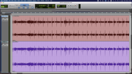
Hi all, I built a 24x2 summing mixer with a passive odd/even input with resistors 5,1kΩ as Re, and a NEUMANN V475-2A mixbuss board before the stereo output. The situation is like this. When I connect the built to my audio interface, if I feed the mixer with -18dBFS 1kHz sine test tone to any of the inputs, I get unity level (-18dBFS) back to the DAW when a variable stereo pot (20kB) that I connected as Rg reads 6,2kΩ. I understand that this is correct and as expected, but, if I raise the level by 1 dB (either from the input or the output of the V475 [Rg])I can hear and see that the tone starts to distort. It seems that the headroom of the V475-2A maxes out at -18dBFS. I have also noticed that the pot raises the level of the output until it reaches 15kΩ, but it is not a clear sine after 7kΩ (1-2 dB) over unity gain, unless I compensate for that level raise, from the input. I connected the pins of the xlr out of the summing mixer to an oscilloscope and I saw that the level of the + and – pin has a ½ level difference. If I sweep the input test tone there is no difference from 20Hz up to about 100Hz but for the rest of the spectrum the – pin is about half the amplitude all the way up to 20kHz. When I feed a stereo signal to the mixer and back to the DAW the waveform is asymmetrical ( I took a screenshot from the DAW) if the levels are higher than -18dBFS. In this example levels are -0.5dBFS I/O. I changed all the electrolytics including the ones in the power rails, but nothing changed. I changed the NE5534AN twice with new op-amps, nothing changed. I measure the power supply, voltage and current and is up to specs. If anyone from the community with electronics skills and knowledge on this board - because I don’t have any-, could give me a hint as where I could possibly look for, his/her help would be much appreciated.
Regards,
Nikos Kefaloyannis
Regards,
Nikos Kefaloyannis
Attachments
these are the documents I have for the V475-2a, schematic and a manual with specifications. It is all in German but with a little help from google translate I managed to read some of it. Surfing in the internet I came across some info that drew my attention. The impedance for the analog I/O of my interface (AVID 192 I/O) is not anywhere stated from the manufacturer, but some people here and there give input Z = 10kΩ and output Z = 50Ω. There is also some remarks about the AVID analog outputs not been able to feed unbalanced inputs with out the use of a transformer. (Not an issue in my case as all my inputs are balanced with 5.1kΩ resistors as Re), but could it be that I am facing an impedance mismatch here?
Attachments
Hi basreflex, thank you for your input. I understand you are asking about the power transformer in the PSU. I used a TALEMA 70032K which is 7VA, 2x115 V to 2x12 V 292 mV, for rectification and regulation I used a board with LM317 that outputs 24.0 V DC to the mix buss. But I have tried an E-I with 14-0-14 secondary, nothing changed, and I also used a bench lab PSU that goes up to 1.5A, and still the results remained unchanged. Now, your remark about the "quasi constant current" think, I understand that fall in the electronics engineering territory and me, being a sound engineer, don't have the background to understand the situation you spotted.
the neumann mixing amp has a very low input impedance by means of a transformer and power opamp. similar to the basic summing opamp with virtual ground input. As the noise gain increases with the number of connected channels, the opamp needs a very low equivalent voltage noise. neumann has solved that problem with a special input transformer.
found it. the transformer is a Haufe RK292 1:2:2. so the input is transfered up 4 times, or the input voltage noise of the opamp reduced by 4 times.
The two secondary windings are connected in series. The schematic place teh transformer in a virtual ground input with very low input impedance as stated in the specificationm of the amp in german.
The two secondary windings are connected in series. The schematic place teh transformer in a virtual ground input with very low input impedance as stated in the specificationm of the amp in german.
So, If I understand it right, I am dealing with an impedance mismatch on the input side? i.e. the very low input Z of the NEUMANN is incompatible with the 50Ω Z of the AVID analog out? and what is the job of the 5.1kΩ resistors (Re) on every pin of every input apart from lowering the line level of the passive sum? How come that Neumann states it can handle 100 signals and I only use 24? I also had the idea that the Neumann “ sees” a high Z input (because of the Re) and that does not change significantly with the number of channels that are active at any given time. At least it doesn’t change any of the “abnormal” levels I see above -18dBFS. My notion was that such “behavior” describes an active amplifier with the wrong bias. Maybe I need to stop messing with the components of the summing device and have a try with a different audio interface? It will be difficult for 24 inputs, but I could try a couple for stereo balanced I/O. Anyone that happened to use a similar analog summer with the AVID / Digi HD interfaces that would like to share his/her experiences?
as can be seen on the schematic, a series resistor is needed between each source and the transformer primary. I assume you have an input transformer on the board, or did you just build the electronics without the input transformer ?
the series resistor value can be chosen, needs to be at least 300 ohms, but this will load your source with that value. 5.1k seems a reasonable value.
the series resistor value can be chosen, needs to be at least 300 ohms, but this will load your source with that value. 5.1k seems a reasonable value.
Last edited:
The schematic is not of a DIY build. It is a eurocard made by NEUMANN model V475-2a. It was used originally in the master bus of the N20 recording/ broadcast console. What I built myself like many others do or buy it custom built is the psu, input output connectors, and an enclosure to house the whole thing. It’s use is as an alternative method to “colour” a multitrack mix already made in a DAW, that to my understanding is partly the side effects of the analog summing through the resistors, mainly the harmonic distortion of the I/O transformers on the mixbuss and selectably some saturation you can get through the variable gain with the control of the Rg. That is, if the device is working correctly, when is a matter of minutes to plug it all in, do some quick routing in the screen of the computer and there you have it. The mix is back in the DAW you A/B the results and you decide if it all worths it or not. If it won’t work as it should, that’s a whole different story, every passing day my DIY attempt is getting closer to the window of my 2nd floor studio.
Attachments
- Home
- Design & Build
- Electronic Design
- NEUMANN V475-2A Summing mixer- asymmetrical output, limited headroom, Help needed.