As I had such a project in my head for a long time, and drivers + WG available, I decided to to put together simple (well, not that simple) 2way.
Initial thoughts of 21W in 2way were not much in favor of that driver, but the more and more I looked at it, the more I liked it. And it paid off.
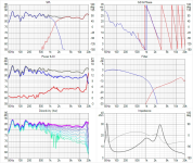
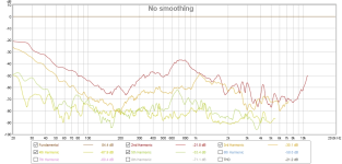
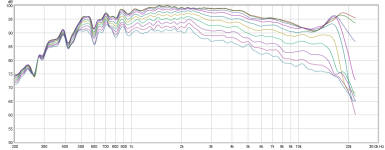
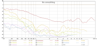
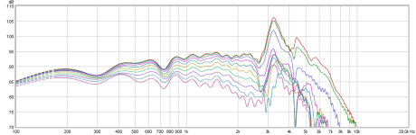
21W - excellent off axis behaviour. Breakup at 3200Hz will need extra care, LR4 and lower crossover point, plus capacitor in parallel to main coil. Distortion measurement confirms breakup mirroring in HD3 and HD5.
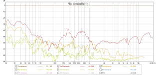
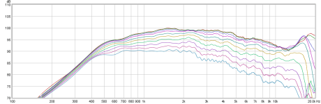
6600 in WG - in simple baffle with almost zero edge treatment I could not hope for better result. Minor dip at 13k was expected, and proved by listening tests to be no issue.
Cabinet: 37l BR 21Hz.
After initial setup and listening there were several challenges:
1. bass was too deep and dry, midrange little bit in the back
2. trebles too forward, mild hiss signature
1. I have done several iterations of damping material adjustment and I lower the value of primary coil to achieve lower baffle step compensation. The result was exactly what I wanted, clear and clean midrange, impressive well defined bass, and good overall balance
2. I had to attenuate trebles above 2kHz by 0.7dB, and take care of 7-10kHz area, and 2.5kHz area. This brought the right balance of detail, clarity and smoothness I know 6600 was capable of.
Measurements were done with no gating, smoothing 1/12. SPL calibrated, distortion measurement with mic distance 30cm, 2.83V drivers and 6V complete loudspeaker.
Full writeup: https://pkaudio.webnode.cz/21w-6600-wg/
Initial thoughts of 21W in 2way were not much in favor of that driver, but the more and more I looked at it, the more I liked it. And it paid off.
21W - excellent off axis behaviour. Breakup at 3200Hz will need extra care, LR4 and lower crossover point, plus capacitor in parallel to main coil. Distortion measurement confirms breakup mirroring in HD3 and HD5.
6600 in WG - in simple baffle with almost zero edge treatment I could not hope for better result. Minor dip at 13k was expected, and proved by listening tests to be no issue.
Cabinet: 37l BR 21Hz.
After initial setup and listening there were several challenges:
1. bass was too deep and dry, midrange little bit in the back
2. trebles too forward, mild hiss signature
1. I have done several iterations of damping material adjustment and I lower the value of primary coil to achieve lower baffle step compensation. The result was exactly what I wanted, clear and clean midrange, impressive well defined bass, and good overall balance
2. I had to attenuate trebles above 2kHz by 0.7dB, and take care of 7-10kHz area, and 2.5kHz area. This brought the right balance of detail, clarity and smoothness I know 6600 was capable of.
Measurements were done with no gating, smoothing 1/12. SPL calibrated, distortion measurement with mic distance 30cm, 2.83V drivers and 6V complete loudspeaker.
Full writeup: https://pkaudio.webnode.cz/21w-6600-wg/
Attachments
-
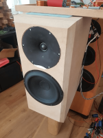 2way 8inch photo.png221.4 KB · Views: 350
 -
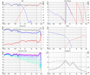
 2way 8inch Vituix Six pack.png111.6 KB · Views: 306
 -
 21W distortion.png64 KB · Views: 239
 -
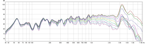 21W FR horizontal 0-90.png57.9 KB · Views: 205
 -
 6600 distortion.png58.9 KB · Views: 212
 -
 6600 FR horizontal 0-90.png70.4 KB · Views: 209
 -
 loudspeaker distorsion 6V.png73.2 KB · Views: 275
Hi Pida, nice!
The breakup is interesting, did you end up adding separate notch filter for it or just the LR4 filter? Is it electronic or acoustic LR4? Could you linger on that some, the electronic filter and audibility of the peak? thanks! @b_force might be interested")
The breakup is interesting, did you end up adding separate notch filter for it or just the LR4 filter? Is it electronic or acoustic LR4? Could you linger on that some, the electronic filter and audibility of the peak? thanks! @b_force might be interested
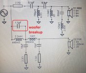
I found the crossover schematics, one of earlier version, the values are now different a bit, though topology is still the same.
It is 4th order electrically and acoustically. 1.1uF capacitor creates parallel notch to suppress 3200Hz breakup. I have been using this for a long time, as it is simple and cheap solution to mitigate woofer breakup. As Purifi shown, this should also suppress HD3+HD5 distortion components, I will do more measurements with/without capacitor soon.
Regarding audibility, after reading Troels 21W 7100 2 way project, I wanted to suppress breakup at least 30dB down. From Troels measurement he used simpler crossover and suppression is 23dB and he mentions this was audible. I tried to listen carefully, also with the ear close to midwoofer and so far did not detect any issues so it seems 30dB is fine. When I did frequency sweeps, breakup was clearly audible, though sounded quite soft and attenuated, not like alu cone breakups => 30dB suppression is likely sufficient.
Attachments
Last edited:
motokok:
It sound very similar to ClassIllu, just goes deeper, a lot.
- port diameter 60mm, length ~30cm (this gave me tuning to 25Hz), two Jantzen ports stuck together. I also inserted felt ring , 6cm long, ~ to the middle of the port, to lower the tuning to desired 21Hz.
- BSC, hmm I do not do bafflestep compensation by "how much", I mean it is actually meaningless to go by number when you have full measurement and can see the full FR. If we consider simulated bass alignment as reference, it shows ~89dB sensitivity if I recall well. From sixpack we can see I ended up with system sensitivity 85-86dB, so from this we can conclude bafflestep compensation was 3-4dB. This number might be misleading, because there is usually 1dB bump at 100Hz and this sets the overall system sensitivity. So I consider bafflestep compensation number to be theoretical concept and not much needed when full measurements are available.
- the sides of the speakers are 1.5m from side walls, and front baffle is ~150cm from the front wall. There are acoustic panels and diffusors on the sides and on the front wall. The room is 30m2.
It sound very similar to ClassIllu, just goes deeper, a lot.
Interesting use case indeed, thanks for notifying!Hi Pida, nice!
The breakup is interesting, did you end up adding separate notch filter for it or just the LR4 filter? Is it electronic or acoustic LR4? Could you linger on that some, the electronic filter and audibility of the peak? thanks! @b_force might be interested
Well done Pida.
Is it a 7" WG ? How would you compare the 6600 VS a basic metal hard dome à la Seas or SB Acoustics ?
The serie 1 mH and // 10 uF + resistor is the smooth baffle step compensation ? Can be seen as two serie 12 dB filter or a 12 dB filter with a damped baffle step compensation ?
Is it a 7" WG ? How would you compare the 6600 VS a basic metal hard dome à la Seas or SB Acoustics ?
The serie 1 mH and // 10 uF + resistor is the smooth baffle step compensation ? Can be seen as two serie 12 dB filter or a 12 dB filter with a damped baffle step compensation ?
diyiggy:
yes, 7inch WG
6600 is one of my favorite tweeters regardless the price. Other favorites on my list are 7100, 7000, TW29RN, T34B, T25B.. to name a few. They all sound different, yet they all are very rewarding to listen to, have detail, transparency, and airy top end, there is certain effortless, lightness yet fullness and body.
In ClassIllu, where I use bare 6600, no WG, I found out it sounded little bit harsh, hiss, attracting the attention, so I used quire narrowband RLC at 6kHz, -1dB, and everything was suddenly perfect. Same happened in this 2way WG project.
Some tweeters I had, measured, and listened to:
Seas DXT - perfect measurement, unfortunately for me unacceptable sound. I replaced it with TW29DN and what a relieve.
https://pkaudio.webnode.cz/sb17dxt/
XT25 and its Scan Speak version - this is nice sounding tweeter, do not have resolution of its expensive siblings though. I do not have problem with its off axis performance.
Seas 25TAC I think, the older and popular tweeter, again, nice sounding tweeter.
Raven Point Source - hardly to judge, this was not my project so I cannot make the conclusions about tweeter SQ itself
Mundorf AMT21 I think. Hmm I expected a lot, hardly to judge, this was not my project so I cannot make the conclusions about tweeter SQ itself
Dayton Mini8 AMT - good measurement, sounds fine for the money
Scan Speak 9700 - this was really good, different sound compared to Revelator and Illuminator tweeters
Scan Speak small flange tweeters - basically all of them sound good
Focal TC9 inverted Ti dome, no no no not good
BW802D2 diamond dome - very good, not easy to make crossover for it.
And a lot of others.......
Last edited:
No, 1mH and //10uF + resistor is part of LR4.The serie 1 mH and // 10 uF + resistor is the smooth baffle step compensation ? Can be seen as two serie 12 dB filter or a 12 dB filter with a damped baffle step compensation ?
In the most cases, extra components for bafflestep compensation are not needed. 2.2mH makes the compensation and is part of LR4 as well.
21W measurement shows FR trend upward, 2.2mH coil effects the trend, larger value starts to point woofer FR downwards.
Pida, did quick simulator experiment regarding breakup with another woofer but with the filter you showed. Purpose for this experiment was to see filter impedance for the woofer as per purifi paper, to inspect series impedance with the driver at the breakup around 3.2kHz.
With the given filter the impedance is about 7 ohms so driver motor distortion components at breakup frequency are attenuated some.

Separate parallel notch between the crossover filter and driver could increase series impedance more, which would reduce distortion even more. Its two more parts though.

There is also opportunity to tweak the second leg, move the impedance peak to the breakup. This would also change the filter slope of course.

Interesting bit is that series impedance with driver is about the same with and without cap/notch, so there is no additional distortion reduction compared to plain LR4 filter, only signal reduction.

Since you seem to be happy with the results, reducing the breakup peak, it seems that additional reduction of driver distortion at the breakup is not that audible. At least, significance is much less than just EQ:ing the peak, perhaps particular to this driver. Anyway
It would be very cool if you have interest to test stuff like this in reality? These filters would somewhat alter the frequency response compared to what you have as I'm not sure how one would actually be able to evaluate what sounds better than others. Perhaps cranking it quite loud could show some difference in sound, distortion well audible.
With the given filter the impedance is about 7 ohms so driver motor distortion components at breakup frequency are attenuated some.
Separate parallel notch between the crossover filter and driver could increase series impedance more, which would reduce distortion even more. Its two more parts though.
There is also opportunity to tweak the second leg, move the impedance peak to the breakup. This would also change the filter slope of course.
Interesting bit is that series impedance with driver is about the same with and without cap/notch, so there is no additional distortion reduction compared to plain LR4 filter, only signal reduction.
Since you seem to be happy with the results, reducing the breakup peak, it seems that additional reduction of driver distortion at the breakup is not that audible. At least, significance is much less than just EQ:ing the peak, perhaps particular to this driver. Anyway
It would be very cool if you have interest to test stuff like this in reality? These filters would somewhat alter the frequency response compared to what you have as I'm not sure how one would actually be able to evaluate what sounds better than others. Perhaps cranking it quite loud could show some difference in sound, distortion well audible.
Last edited:
tmuikku: thanks for nice analysis.
I was thinking of following experiment:
I was thinking of following experiment:
- I would design series and parallel notches, both doing the same breakup reduction
- impedance measurement for both, and just midwoofer crossover section
- distortion measurement for both
- and listening tests of course
b_force: I will add graphs with gated responses. I use REW, no problem to add it. I looked at the gated responses as well, to have another view on the measured responses. For my recent projects I started to use no gating, just smoothing. When weather allows, I will do outdoor measurements.
And nearfield, ~10mm from dustcap, yes it will be better to judge the effect of notches.
And nearfield, ~10mm from dustcap, yes it will be better to judge the effect of notches.
The issue with just smoothing, is that you don't know if certain peaks or dips are a system or driver issues, or a interference problem. It also covers up many many other issues.
Audio Precision has an excellent guide on how to perform and stitch gated measurements with nearfield measurements (incl bafflestep correction). Which is really easy to use at home.
https://www.ap.com/wp-content/uploads/2021/09/AppNote-Loudspeaker-EA-Measurements.pdf
https://audioxpress.com/news/application-note-loudspeaker-electroacoustic-measurements
We live in a very small appartement atm and I have no trouble measuring from around 180-220Hz and upwards with the right window type.

Nice! Also, according to the previous experiment it would be really cool if you tweaked the xo a little, move xo bit higher up. This would increase DI hump, but could be tuned to really reduce distortion. First the tweeter would have less excursion and second the woofer xo can be the same as now but tweaked a little to get the impedance hump that is in series with the driver to the breakup frequency.tmuikku: thanks for nice analysis.
I was thinking of following experiment:
- I would design series and parallel notches, both doing the same breakup reduction
- impedance measurement for both, and just midwoofer crossover section
- distortion measurement for both
- and listening tests of course
So it would be interesting comparison which is more meaningfull, DI or some distortion reduction
perhaps the distortions could be tweaked, or something. Or maybe noticed it is not that importantedit. at least, would be interesting to know what you think about it? thanks!
Last edited:
Cone edge resonance I assume. Wavecors had the dip lower, around 400Hz.Any comment on the 21W dip 750hz? You had something similar with Wavecor 8" if I remember.
I managed to shift Fc up by ~100Hz. Tomorrow I will check what it means for woofer section impedance around that frequency.Nice! Also, according to the previous experiment it would be really cool if you tweaked the xo a little, move xo bit higher up. This would increase DI hump, but could be tuned to really reduce distortion. First the tweeter would have less excursion and second the woofer xo can be the same as now but tweaked a little to get the impedance hump that is in series with the driver to the breakup frequency.
So it would be interesting comparison which is more meaningfull, DI or some distortion reduction
edit. at least, would be interesting to know what you think about it? thanks!
Attachments
- Home
- Loudspeakers
- Multi-Way
- New project: 8inch 2way, WG, Scan Speak