Started on a new project for a capacitor ESR tester.
A ac waveform is applied to the cap under test.
The output is monitored and measured by an a2d converter.
This is USB'ed to the PC and the pc prints out ESR ohms.
A sledgehammer to crack a nut maybe.
The output of cap is peak detected and smoothed into a buffer then a2d.

A ac waveform is applied to the cap under test.
The output is monitored and measured by an a2d converter.
This is USB'ed to the PC and the pc prints out ESR ohms.
A sledgehammer to crack a nut maybe.
The output of cap is peak detected and smoothed into a buffer then a2d.
Good idea, keep us informed.
Will you publish the whole project, including PCB and necessary software?
Will you publish the whole project, including PCB and necessary software?
There's quite a bit to it.
1/ Circuit and PCB design
2/ Embedded microchip harmony embedded software.
3/ PC interface software.
You will need a Microchip pickit or snap to program the PIC.
I will see what I can do, waiting for pcb's at the moment.
1/ Circuit and PCB design
2/ Embedded microchip harmony embedded software.
3/ PC interface software.
You will need a Microchip pickit or snap to program the PIC.
I will see what I can do, waiting for pcb's at the moment.

Somewhere between 10k and 100k as a starting point.
I am using a PIC32mx230 OC4 output which runs automatically.
I can set the frequency to pretty much anything I want.
Its a square wave so its a broad band of frequencies.
Fundamental plus odd harmonics.
I am using a PIC32mx230 OC4 output which runs automatically.
I can set the frequency to pretty much anything I want.
Its a square wave so its a broad band of frequencies.
Fundamental plus odd harmonics.
Might be a good job for some DSP. You could run a Python script on a PC to extract the data.
I like the idea of a square wave.
A nice bit of math to get your teeth into!
😀
I like the idea of a square wave.
A nice bit of math to get your teeth into!
😀
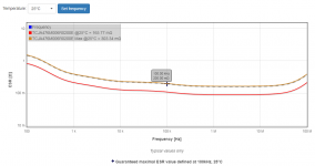
Indeed, because ESR is virtual parameter, without actual physical existence. It is mathematically related to the loss tangent, Q, parallel damping, etc.As you know, ESR is not a constant. It varies with frequency. Here are ESR-vs-frequency plots from Cornell Dubilier and from AVX.
_
It is a measure of the losses, but it cannot be used as a scalar quantity with the Ohm's law for example: a 1µF polypropylene capacitor might have an ESR (I mean the true ESR) of a fraction of an ohm at 50Hz, but if you place it in series with a 1V AC source and an ammeter, it is not going to register amperes of current, but ~300µA.
What the tester presented here measures is the magnitude of the total impedance, including ESR, ESL and Xc.
This does not make it useless, but it is not an ESR meter, and if E-caps are measured with it, it will give results totally different from the ones published in the datasheet (which are true ESR).
To measure the ESR, you need a vector-sensitive instrument, not just a simple scalar detector.
I think I have shown some examples of vector ESR or tan delta meters on this forum.
A scalar impedance meter can be used to assess the bypassing efficiency of a capacitor at high frequencies, but not for much else
How does the vector ESR work ?
As it stands I can output a set frequency or a even a ramp of frequencies to cover a bandwidth.
As it stands I can output a set frequency or a even a ramp of frequencies to cover a bandwidth.
Attachments
Last edited:
For the real part of the impedance, the measurement needs to discriminate the in-phase response for the driving fundamental - aka a synchronous detector.
Yes, a synchronous detector can be made very simply, with an analogue switch like CD4016 or 4053.
You just drive its control pin with the stimulus squarewave, and include it in your opamp rectifier, instead of a diode, and that's it.
Side benefits over the diode detector is that it is not going to be limited at high-frequencies + low-level, and thanks to the correlation, it will have an excellent rejection of parasitic signals, meaning you can push the amplification to very high levels if needed (very large caps/low stimulus current).
Such a switch is just barely more expensive than the diode option.
Note that it might be advantageous to swap the C and R in your setup with the sync-rect:
it will allow you to use a very small measuring resistor having minimal parasitic effects on the phase.
You can then insert a large gain amplifier, to compensate.
In this case, the reference signal for the switch needs to be in quadrature, but that is not a problem for you since you use a µC to generate the signals
It may be worth reading through the ESR meter(s) prepared by Jay_Diddy_P on eevblog (ESR Meter Adapter Design and Construction - Page 1). I set that circuit up (well almost the same) and it was certainly accurate for resistors, but I could only make subjective measurements for ESR of caps (although they seem reasonable).
Testing at 100kHz can require more attention to the analog mux switch (eg. 4053) and layout, as leakage signal increases, and I ended up just 1kHz or 10kHz. Maybe the PIC can acceptably do the oscillator and mux functions. I certainly found the use of an instrumentation amp a benefit due to ease of offset trimming and stable but high gains if you want an analog display of V=Ohm.
Testing at 100kHz can require more attention to the analog mux switch (eg. 4053) and layout, as leakage signal increases, and I ended up just 1kHz or 10kHz. Maybe the PIC can acceptably do the oscillator and mux functions. I certainly found the use of an instrumentation amp a benefit due to ease of offset trimming and stable but high gains if you want an analog display of V=Ohm.
A good, SOTA example. There are many ways to skin a cat though, and I often use slightly different schemes.
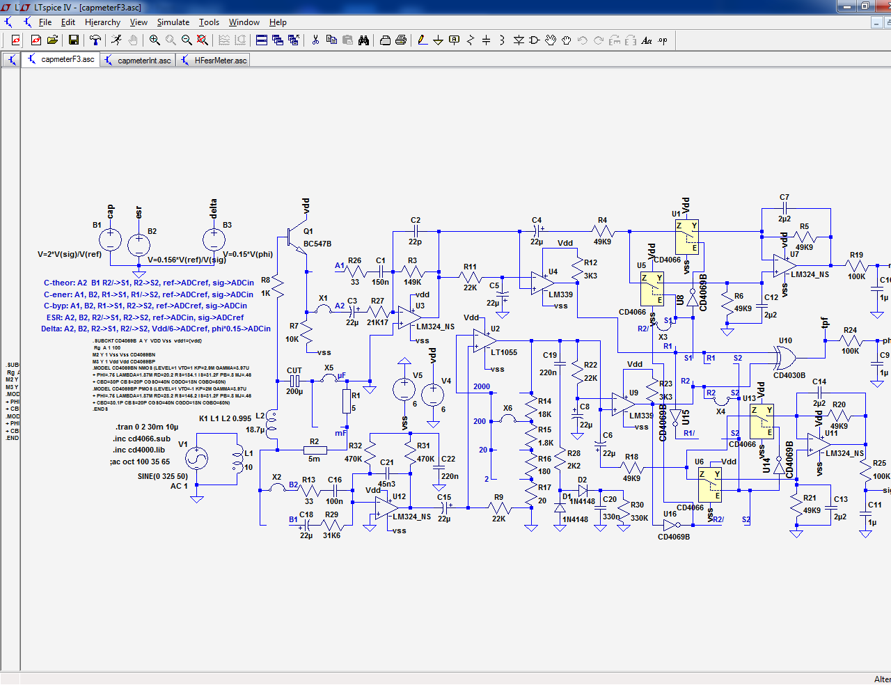
The absolutely minimalist option uses a single switch; it can be 1/4 of 4016/66, a FET or a small MOSFET.
It is simplistic and works OK at low frequencies, but it struggles at higher frequencies.
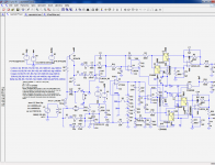
Here is an example (U5, U11 and U6, U7).
The switch and the 10K resistor can be swapped to reverse the phase:
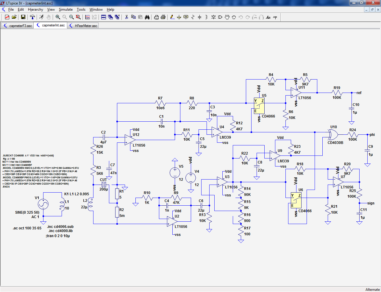
Here is another example, using 4053's (simulated with switch and inverter).
This time, the input resistor is upstream of the switches, and the integration is performed at the opamp level.
The gain is 1/2 than the peak rectifier used by Jay Diddy, but the switches are completely protected, they see 0V all the time across them, they just steer currents, and the averaging at the opamp level gives a much better immunity against imperfections, like small ringing due the inductance of the test leads:
It is also possible to insert an amplifier (here 20dB thanks to the transistor) between the CUT and the sync-rect. It is advantageous, because the DC accuracy does not matter at the AC level. This means that the DC post processing doesn't need to be particularly stable or low offset:
In general, since the 4053 has 3 operators, it is possible to connect another operator in parallel, but with the control in antiphase and the input to the GND or better, the GND sense line in 4-wire configuration.
This will restore the gain to that of the peak-detecting circuit, but without its drawbacks, and with some charge-injection cancellation.
These are just a few examples, it is a vast subject
The absolutely minimalist option uses a single switch; it can be 1/4 of 4016/66, a FET or a small MOSFET.
It is simplistic and works OK at low frequencies, but it struggles at higher frequencies.
Here is an example (U5, U11 and U6, U7).
The switch and the 10K resistor can be swapped to reverse the phase:
Here is another example, using 4053's (simulated with switch and inverter).
This time, the input resistor is upstream of the switches, and the integration is performed at the opamp level.
The gain is 1/2 than the peak rectifier used by Jay Diddy, but the switches are completely protected, they see 0V all the time across them, they just steer currents, and the averaging at the opamp level gives a much better immunity against imperfections, like small ringing due the inductance of the test leads:
It is also possible to insert an amplifier (here 20dB thanks to the transistor) between the CUT and the sync-rect. It is advantageous, because the DC accuracy does not matter at the AC level. This means that the DC post processing doesn't need to be particularly stable or low offset:
In general, since the 4053 has 3 operators, it is possible to connect another operator in parallel, but with the control in antiphase and the input to the GND or better, the GND sense line in 4-wire configuration.
This will restore the gain to that of the peak-detecting circuit, but without its drawbacks, and with some charge-injection cancellation.
These are just a few examples, it is a vast subject
Attachments


Last edited:
This is valid only for some schemes: it is applicable to the third example I gave (and all the cases where the switches are upstream of the input resistors)In general, since the 4053 has 3 operators, it is possible to connect another operator in parallel, but with the control in antiphase and the input to the GND or better, the GND sense line in 4-wire configuration.
This will restore the gain to that of the peak-detecting circuit, but without its drawbacks, and with some charge-injection cancellation.
An important point worth keeping in mind with synchronous schemes: the switch control signal has to be exactly in phase with the current in the R-C tested network.
In principle, this would mean deriving the signal from the voltage across R, but in practice if the voltage across R is >>> than the voltage across the cap (R large and C large), using the driving squarewave as a reference is acceptable.
If the opposite is true (R small and C small), use the 90° shifted driving signal.
In both cases, the cap reactance and the resistance have to be widely different.
If they are similar, you need to derive the switch control from the voltage across the resistor, which adds complications.
Failing to respect these conditions will cause a "leak" of the capacitive reactance into the ESR. Not a major problem if they are similar, but if you try to measure the true ESR of a 1µF polypropylene at 50Hz, it is extra important: the ESR will be 5,000 times smaller than the reactance, and the slightest leak will corrupt the measurement
While waiting for pcb I got stuck into some pc software.
To keep things simple I get the user to input capacitance then I can work out Xc.
If I subtract capacitor Xc from total resistance seen I get ESR in ohms.
To keep things simple I get the user to input capacitance then I can work out Xc.
If I subtract capacitor Xc from total resistance seen I get ESR in ohms.
In the vector world, things are a bit more complicated : Z²=ESR²+X²c
Thus ESR=sqrt(Z²-X²c), but in practice this will only be workable when ESR and Xc have not too different values.
For smallish values of ESR, Xc and Z will become indistinguishable: Z is the hypotenuse of a right triangle, and when ESR is small, the other triangle side becomes almost equal to the hypotenuse
This procedure chooses a test frequency for ESR measurement, where there is just about the least possible pollution by Xc and by Xesl.
Presto. You've found a test frequency "fTEST" which is midway between the capacitance-dominated region at low frequencies, and the equivalent-inductance-dominated region at high frequencies. Run your ESR test procedures at fTEST and be happy.
- Measure |ZL| = magnitude of impedance at a low frequency, e.g., 100 Hz
- Calculate CL =1 / ( 2 * pi * 100Hz * |ZL| )
- Measure |ZH| = magnitude of impedance at a high frequency, e.g., 750 kHz
- Calculate LH = |ZH| / (2 * pi * 750kHz )
- Calculate fTEST = 1 / [ 2 * pi * sqrt( CL * LH ) ]
- Home
- Design & Build
- Equipment & Tools
- New project, ESR tester.