Ok, so I have a 3886 amp that I have built, and everything is wonderful so far. Sound quality is excellent. The only problem I have found is that when you put your ear up to the speaker, you can hear a little bit of noise. There is some hiss, some 60 Hz hum, and some rapid ticky noise. It's low... probably wouldn't notice unless you were looking for it, but I want it gone.
I knew that I would have to perform some experimentation with grounding schemes to finalize the assembly, but I don't want to connect something that shouldn't be connected.
So here's a list of everything I have been considering connecting to a star-ground:
- The gnd input (between the AC inputs) on the power supply board
- The gnd output (between the +V and -V outputs) on the power supply board
- The green wire coming in from the power mains
- The metal chassis the amp is built in
- The aluminum heatsink the chips are bolted onto
- The neutral wire coming in from power mains which is connected to two of the transformer primaries
- Two of the wires coming out from the transformer secondaries (which go to the gnd input of the power supply board)
- The shielding of the RCA input connectors
- The "ground" next to the "out" on the amp pcbs which goes to the speakers
- The ground input between the +v and -v inputs of the amplifier pcbs
So, what should be connected? None? Some? All?
Grounding of more often done wrong than right.
I found this article (http://www.diyaudio.com/forums/diya...udio-component-grounding-interconnection.html) a very helpful starting point. After reading (part of) it, you're questions will most likely be answered.
I found this article (http://www.diyaudio.com/forums/diya...udio-component-grounding-interconnection.html) a very helpful starting point. After reading (part of) it, you're questions will most likely be answered.
You should not connect the neutral wire to ground.
You do not need to connect the heatsink to ground if it's not exposed. Be aware that the non-isolated versions of the LM3886 have V- on their tab.
The input and output grounds on the power supply board should already be connected to each other via the board.
You do not need to connect the heatsink to ground if it's not exposed. Be aware that the non-isolated versions of the LM3886 have V- on their tab.
The input and output grounds on the power supply board should already be connected to each other via the board.
uzernaam, put up a picture of your amp (insides) and then lets take a look to see if we can get the noise down.
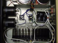
Okay, here are some pics:
(It's my first amp, didn't build it to look pretty. Was doing it for experience... the next one will be much more "as it should be")


(It's my first amp, didn't build it to look pretty. Was doing it for experience... the next one will be much more "as it should be")
Construction looks neat (unfortunately that is no gaurantee of good sound or low noise!). To kick off, here are some pointers to your questions above and from what I can glean from the pictures
1. Your input connectors must not make contact to the chassis other than via the screen cable back to the pre-amp PCB's. Unsolder the connections to your board, and measure with a meter to make sure this is the situation. Same for your speaker connectors and headphone connector if you have one fitted.
2. It looks like you have single PCB's for each channel, both for the power amps, and pre-amps. The 0V of each of these boards must be wired separately to the star ground - but see notes below for the detail on how to do that.
3. The order of the wiring connection to the star ground is important if you want the lowest noise. 'T' off about 0.5cm of thick wire from the exact centre where the main filter caps are joined. Wire the power amp OV lines to this 'T' point. Then make a second 'T' off from the star ground (again about 0.5cm of cable, also thick), and connect your pre-amp boards 0V to this point.
4. The above approach ensures you have no common ground impeadance coupling between the filter caps, the power amp and the pre-amp boards and gives the lowest noise.
4. From the star ground where the main filter capacitors connect, run a solid piece of cable to the chassis. This must be the ONLY connection to the chassis from the 0V.
5. On the incoming earth cable, connect it solidly to the chassis in one place only - usualy this is done quite close to the mains inlet receptacle. This must be the ONLY place the incoming earth is connected to.
6. Speaker 0V returns. The 0V returns from the speaker should be connected between the where the filter caps join (to form the 0V) and the power amp 0V 'T' point.
7. The two wires comming from the transformer that go to the 0V point should connect right where the filter capacitors join, and nowhere else.
8. Remember to twist tightly together the secondary wires coming from each secondary. In the picture above, you have a bunch of wires loosely hangining together, very long and connected via a 'chocolate block' screw terminal to the rectifier and filter capacitor board. There are large capacitor charging pulses flowing in these wires (with harmonics up into the KHz range), and because source and returns wires on each winding are not tightly bound together, they form a great radiator - which is probably getting picked up by the input wiring. You need to look at this part of your amp.
9. Heatsinks don't need to be earthed, but if you are using isolating heatsink washers, then I think its good practice to earth (to the chassis) as part of the mechanical construction.
Last edited:
As usual I don't have the same opinion on connecting the signal GND directly to an "earthed" chassis. Use a heavy resistor of 10 Ohm to lift signal GND from PE/safety earth. Please check the way Nelson Pass does this with either a CL60 thermistor or a diode bridge as it seems an elegant solution. Please check the schematics of some Pass DIY products to see what I mean. Till now I used a heavy resistor paralleled with a 10 to 100 n 250V cap so stray RF will be guided/shorted to PE/safety ground.
You don't want pollution from PE to come into your audio circuits but PE should be connected to the metal chassis for safety purposes.
You don't want pollution from PE to come into your audio circuits but PE should be connected to the metal chassis for safety purposes.
Last edited:
Ok, so I have a 3886 amp that I have built, and everything is wonderful so far. Sound quality is excellent. The only problem I have found is that when you put your ear up to the speaker, you can hear a little bit of noise. There is some hiss, some 60 Hz hum, and some rapid ticky noise. It's low... probably wouldn't notice unless you were looking for it, but I want it gone.
I'm unfamiliar with your amplifier, but your ear-up-to-the speaker test is pretty sever. 😱 I would expect some hiss and hum, especially if the speakers are very efficient! Also, if your amplifier is tube, you will get some hum unless your power supply is in the next room and the heaters are run on regulated DC current. 🙂 Be happy if you don't hear anything from your listening position.
BTW, I used to be an engineer designing OEM car radios. In a parked car (engine not running) with an ear closed to a speaker, you can hear noise in the micro watt range! No amplifier is quiet enough to be completely silent under those conditions.
Bobby Dipole
The input and output connectors on the back plate of the chassis are isolated from the chassis. There are plastic insulators that ensure this. I measured resistance with an ohmmeter after I installed the connectors into the plate (before any wires were connected to them) and there was no connection between them.
Ok, what about the other points?
In any properly designed and wired solid state amp you should not hear any hum with your ear right againt the speaker cone.
Noise (thermal) - if you put your ear next the the tweeter, you may hear some hiss, but the level is very dependent on the amplifer gain from input through to output, the source impedance and howthe gain iss distributed throught he various stages. Most modern IC's are pretty goo in this regard.
Regarding signal ground connection to the chassis earth and the point Jean Paul makes, I'd sort the basic wiring out first before putting any ground lifters in place. There is always a safety aspect involved here, so proceed wisely. Personally, I dont think resistors between the 0V and earth are as good as two back to back 6A diodes with a 10 Ohm resistor in parallel.
I have no ground lifters in my system and its very quiet and passes the 'ear in cone' test - details on my website below.
Here is how my ground is done. I have no ground lift and my system also passes the 'ear in cone' silence test.
The signal connects where the ground comes into the amp boards.
The speaker connects directly between the largest caps on the amp boards.
There are 2 smaller electrolytic and 2 film caps between the largest caps and the LM3886's.
The signal connects where the ground comes into the amp boards.
The speaker connects directly between the largest caps on the amp boards.
There are 2 smaller electrolytic and 2 film caps between the largest caps and the LM3886's.
Attachments

Thats not a bad arrangement.
I would do a few things differently personally to reduce common impeadance distortion (which only manifests itself when there is signal)
1. Instead of joining the grounds of the two amplifiers and then running a common 0V to to your ground lug, I'd keep the grounds separate. Another way of looking at this is simple keep the bottom of the 'T' connection very short. The reason is to minimize common impeadance coupling between the amps.
2. Speaker returns -assuming the amps are single ended - I'd bring those all the way back to the ground lug - and preferably right to the filter cap 0V connection points.
By the way, in my earlier post I refer to two 'back to back' diodes. Some people may read this as two diodes in series facing the opposite way. What I meant was 'anti-parallel' connection so the current can flow in both directions once the voltage across the diodes is above about 0.6V.
for home use micro watt range is noisy.you can hear noise in the micro watt range! No amplifier is quiet enough to be completely silent under those conditions.
0.1mVac into 4ohm is ~2.5nW
Some amplifiers can be as much as 10dB quieter than that, i.e. <1nW of noise.
Thats not a bad arrangement.
I would do a few things differently personally to reduce common impeadance distortion (which only manifests itself when there is signal)
1. Instead of joining the grounds of the two amplifiers and then running a common 0V to to your ground lug, I'd keep the grounds separate. Another way of looking at this is simple keep the bottom of the 'T' connection very short. The reason is to minimize common impeadance coupling between the amps.
2. Speaker returns -assuming the amps are single ended - I'd bring those all the way back to the ground lug - and preferably right to the filter cap 0V connection points.
Neither of those would work in my case, as the PSU and amps are in separate cases. The single ground between them is in the cable connecting them.
Separate ground returns from the amps to the PSU would still lower your common impeadance distortion.
Neither of those would work in my case, as the PSU and amps are in separate cases. The single ground between them is in the cable connecting them.
That's a recipe for a not particularly transparent system in my experience. Have you experimented with implementing star earthing? Bonsai's right, you'd reduce common impedance distortion.
No I haven't experimented because at the moment I don't have the money to experiment. I plan on eventually moving the power supply into the same case as the amp, so I can try it then.
- Status
- Not open for further replies.
- Home
- Amplifiers
- Chip Amps
- Noise Problems - What To Ground ?