Hey there. I just purchased two Electra voice S 15 PA speakers. One of the speakers, has a crossover that’s not working. Both the horn and the speaker are good, but when connected to the crossover, only the woofer is getting signal. Here are some photos of the crossover. Any suggestions as to where I should begin to troubleshoot. I only have a multimeter. Any help would be greatly appreciated. Much thanks!
Attachments
-
 90FD7F8B-E5EA-415A-8B53-90331EB5FBEA.jpeg309.5 KB · Views: 116
 -
 A0D1B7D0-8C01-4115-8B6B-378A3B41DC7A.jpeg296.2 KB · Views: 101
 -
 601AD9BE-68C8-456E-BD95-390555BC3A35.jpeg283.6 KB · Views: 106
 -
 543FF85C-D8E0-4DB8-A14D-A9E134F1B927.jpeg322 KB · Views: 108
 -
 AA98F78A-9845-417C-BEAB-100F7E082532.jpeg254.3 KB · Views: 101
 -
 6678381F-00DE-437E-9E2E-751133ABE30B.jpeg364.6 KB · Views: 111
I will give this a try. A photo of what the board looks like under component R1 ( the big white thing ) would be helpful.
Clearly R1 got hot as hell and may have replaced in the past. Lots of oxidation present on component terminals makes me think that the speaker was in a very damp environment.
Not all is lost, and it may be reparable.
Clearly R1 got hot as hell and may have replaced in the past. Lots of oxidation present on component terminals makes me think that the speaker was in a very damp environment.
Not all is lost, and it may be reparable.
Check the resistor and ptc (yellow) for shorts or infinite resistance.
Try tracing the schematic.
Try tracing the schematic.
Here are some more photos. Also, Is the big white thing the resistor? And, there are two yellow things big rectangular, and tiny and round.
Attachments
-
 FC29A220-5CD8-4AF7-8C21-E04CAB86BB5F.jpeg274.6 KB · Views: 47
 -
 140CB7BA-933B-459B-8D06-27FDC72C837D.jpeg270.1 KB · Views: 45
 -
 AA1225B0-4CAB-4B67-BD76-EF33EB24F8B2.jpeg275.4 KB · Views: 46
 -
 54CC6929-E05A-4DB1-B3D6-811CBF150839.jpeg300 KB · Views: 46
 -
 5F8F4232-5EED-4B5D-AB92-2A8677A64BDD.jpeg337.3 KB · Views: 49
 -
 1B0E2404-9F5D-4F9E-A4E7-83AC3877263A.jpeg300.9 KB · Views: 45
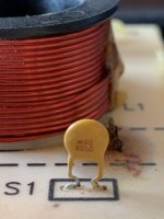
The white R1 is a 20W(watt) 10 ohm resistor, S1 is a PTC thermistor, a resistor with a Positive Temperature Coefficient, it's resistance increases with increasing temperature.
Two capacitors (black and yellow), two coils.
Two capacitors (black and yellow), two coils.
I traced out the PC board and think I have it correct even though the L1, C1 configuration seems unusual. It looks like J1 was removed at some point with side cutters but will not create any problems. Regarding tweeter output, check resistance across R1. It should read 10 Ohms (or less as its in parallel with S1). If it reads high or open, then both S1 and R1 need to be replaced. If R1 reads 10 Ohms +/- 1 or 2 Ohms, then S1 is likely defective. If R1 reads 10 Ohms or less, than the next culprit would be C2. C2 is hard to test with a multimeter unless the meter has a capacitance test function. Without the board connected to anything, C2 should read true.

One leg of C1 should go to (-) not in parallel with the coil. But...strangely, following the PCB, it seems placed in series
Yea, that was my reaction as well. As drawn, it produces a deep notch, not a low pass. The woofer inductance above the notch frequency may play a role. Has anyone else seen a topology like this?

Hey it's wednesday, keep us informed!
Science of logic indagation would tell to:
remove both crossovers
make ext connection for each speaker ( crossover outside is always welcomed)
make A to B, C to D and all the possible permutations, maybe first
analyze the two XO boards to see if any ... difference is visible
I found only a 6 pages pdf regarding S15s and bla bla bla Fc is 2900 Hz!
Can we discuss the effect of a 1 uF cap in terms of equalization of a cd+horn! Eh?!
Naaah..!
The notch effect of the LC net is also discussable!
One thing that someday I'll try...
Stick a 0.33 uF to a coil!
Hey there. Thanks for your patience and advice! I only measure .6 ohms across R1. And…there is no continuity across the black 1uf capacitor. Do you there continuity across all others and the coils. Do you think the capacitor is the only culprit, or does the resistor need to go as well??
- Home
- Loudspeakers
- Multi-Way
- Noob needs help (please) with Electro-voice crossover