I noticed the CL-60 is commonly used for F4,F5 projects for inrush current limiting, rated at 10ohms 5Amp.
In a 240v world is the same part applicable, or should i double the resistance rating and half the current rating? For example would the CL-190 rated for 25ohms 2.4Amp be more suitable, or have i got the wrong end of the stick?
My application will be an F4 with an Antec 500va 18v transformer feeding two banks of 88,000uf caps.
I think you have the right end of the stick. You need a reasonable match between the NTC and the application, as a poor match will lead to smoke (if it gets too hot) or weak action (if it starts with too low a resistance, and then stays too cool).
Yes, you need to match the NTC to the duty.
the CL60 works well in the USA and other 100/115Vac Countries.
Two in series would work well in 220/240Vac Countries. But costs twice as much and has double the Joule rating that may not be required.
However, your 25r NTC is more suited to very large 240Vac transformers. say 1kVA to 1.5kVA
Assume worst case and a primary resistance of 0r5
The total resistance seen by the mains at switch on is 25r5
The rms current during that switch on moment can be as high as 240/25.5 = 9.4Aac
I have found that typically the fuse that won't blow can be half that value i.e. T4A or T5A
These fuses can run a 960VA and 1200VA transformers.
A 500VA would run on a T2A fuse and thus a maximum start up current of around 4Aac can be used to determine the soft start resistance.
240Vac/4Aac = 60r
Subtract the primary resistance, usually fairly insignificant at these VA and then select your NTC or resistors.
Two of your 25r NTC in series will probably start a 500VA transformer fitted with a close rated T2A fuse.
And bypass the NTCs after a couple of seconds.
Last edited:
Thanks for that, it was starting to make a little more sense until i took your formulas and did a little reverse engineering. A CL-60 with 120v would allow for 120v/10r=12Aac which has me confused as its a lot more than a 400va or 500va transformer on full load, then its spec sheet says 5amp, is that the max current the device can take, or the max current it will pass though when hot?
300va @120v = 2.5Aac
400va @120v = 3.3Aac
500va @120v = 4.1Aac
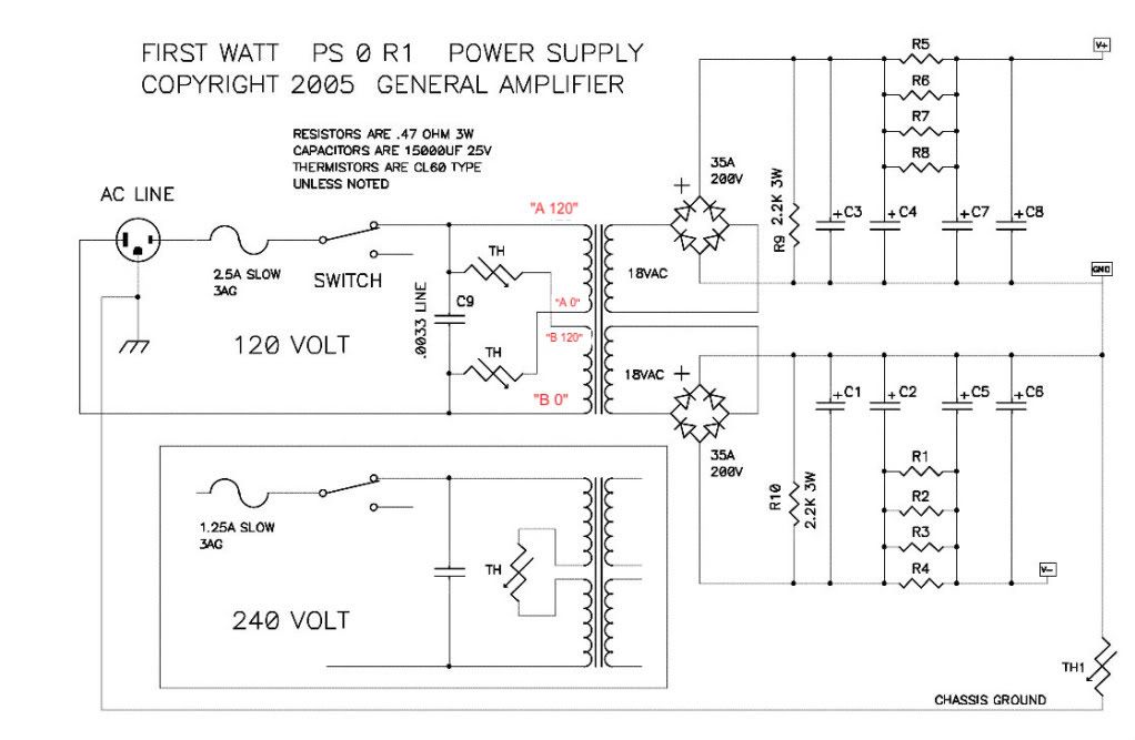
Then looking at the below schematic, i believe FirstWatt used a 300va transformer which would draw 2.5amp on full load, so the 2.5amp slow blow fuse makes sense to protect the transformer. But the use of two CL-60 NTC's has me totally stumped as there is one for each winding, and therefore each is only taking half the load. Am i just being a little bit dim here as i dont see the math that spec'd that part for the application?
In relation to the 240v setup, a 500va@240v = 2Aac, so a 2amp slow blow fuse makes sense there too. But without getting my head around the above i cant begin to spec the NTC for 240v when you are dealing with a single NTC joining the two windings together.
Is there some fundamental rule i don't know about, for example do you allow the start up current to spike 2-3 times the nominal rating of the transformer or something?
300va @120v = 2.5Aac
400va @120v = 3.3Aac
500va @120v = 4.1Aac
Then looking at the below schematic, i believe FirstWatt used a 300va transformer which would draw 2.5amp on full load, so the 2.5amp slow blow fuse makes sense to protect the transformer. But the use of two CL-60 NTC's has me totally stumped as there is one for each winding, and therefore each is only taking half the load. Am i just being a little bit dim here as i dont see the math that spec'd that part for the application?
In relation to the 240v setup, a 500va@240v = 2Aac, so a 2amp slow blow fuse makes sense there too. But without getting my head around the above i cant begin to spec the NTC for 240v when you are dealing with a single NTC joining the two windings together.
Is there some fundamental rule i don't know about, for example do you allow the start up current to spike 2-3 times the nominal rating of the transformer or something?
My understanding is that an NTC said to be '10 ohms, 5A' means that it has 10R resistance when cold and can carry up to 5A continuously when hot. It may be able to pass considerably more than 5A for a brief time during startup.
Yes, an NTC can pass a very large current for a short period. That's where the joules/energy dissipation comes in. The datasheets show a calculation method from a very low source impedance into a capacitor load, i.e. a slow charge duty. This is what is at the input of a mains powered SMPS.
I have not fully converted their slow charge calculation method to apply to a soft start for a transformer.
So instead I simplify to considering it all as resistance and use Ohm's law. The transformer primary is actually quite different from my simplification, but the result for the fuse rating relative to the limited value of the current seems to work.
The resistance value has a big range of acceptable values, especially if you increase the fuse to well above the close rated value.
That's what the adoption of the CL60 for 110/116Vac is relying on. Simple = one recommendation that works for all.
Last edited:
'10 ohms, 5A' means that it has 10R resistance when cold and can carry up to 5A
and when the rated current is flowing, the voltage drop is below 1 volt, dissipation is not so high, it is hot because it is small in mass...this is why i wouldn't bother with a relay shorting it out in use...i have been using these and never had a failure in my builds...
Last edited:
And you report a very high sag in your supply rail voltage when tested to maximum power.and when the rated current is flowing, the voltage drop is below 1 ohm, dissipation is not so high, it is hot because it is small in mass...the is why i wouldn't bother with a relay shorting it out in use...i have been using these and never had a failure in my builds...
Some of that sag will be due to the added source impedance that your mains transformer is seeing.
I have in the past suggested that your high sag was too high and suggested that you look again at your power supply design.
You retorted with "your supply sag values are impossible". You virtually told everyone that I was making it up, i.e. lying !
i did not use NTC resistors that time, i used 10 ohm/50 watt dale resistors shorted out by relay after a delay of 3 seconds....my power traffo was a big, 2 inch center leg EI stacked to 3 1/2 inches and was handbuilt by me....
i will have a chance to repeat my testing after 20 years, i am rebuilding that amp, and will document my findings complete with pictures......
FYI, i use NTC's mostly on tube amps that i build.....
it could very well be that because the E's that i used had a 1/8 inch gap at center leg so that that will explain in part the drop in rails,
i will rebuild with a new traffo of same dimensions, this time without the gap at center leg and see what gives...😉
i suggest that you look at the service manual of the Pioneer Spec 2 amps...
tell us what you see...😉
i will have a chance to repeat my testing after 20 years, i am rebuilding that amp, and will document my findings complete with pictures......
FYI, i use NTC's mostly on tube amps that i build.....
"your supply sag values are impossible"
it could very well be that because the E's that i used had a 1/8 inch gap at center leg so that that will explain in part the drop in rails,
i will rebuild with a new traffo of same dimensions, this time without the gap at center leg and see what gives...😉
i suggest that you look at the service manual of the Pioneer Spec 2 amps...
tell us what you see...😉
I don't have any Pioneer manuals
It is easier for me to just measure the amplifiers that I have built.
I have reported the sagged voltages of at least two and possibly three, or four, in my time here.
It is easier for me to just measure the amplifiers that I have built.
I have reported the sagged voltages of at least two and possibly three, or four, in my time here.
It is easier for me to just measure the amplifiers that I have built.
I have reported the sagged voltages of at least two and possibly three, or four, in my time here.
so if another's result are different from yours, then it must be wrong, is that it?
I did a bit more reading and looked up the datasheets for a few different manufacturers which were a little more enlightening. Seems they are really intended to sit at the beginning of a switching power supply but most of the data was applicable. Also confirmed the ohm rating is @25c, and its resistance decreases as it heats up which is the opposite of what i thought. Amp rating is the max steady state load.
Something about it doesn't really sit right with me as it will never fully go away leaving you with a bit of resistance in the primary winding all the time, provided it stays warm, provided you get the sizing right for your load. It would be preferable to be able to switch it out or it makes a $200 power cable kind of pointless. ...joke!
Very interesting read, but opens a whole other can of worms. I did purchase the soft start PCB with the amp but figured it would be prudent to build the amp with a simple NTC first, than add the soft start. The lack of information on the product page is a little concerning, and no mention of 240v operation doesn't instill a lot of confidence either when its generating its own DC power supply from the live mains. Surly all the voltages will be double, and the time delay will be all scewed if its build around 120v operation?
At the moment i'm looking at options on eBay that have a small transformer on board to generate the local DC supply, bank of NTC's, and a time delay circuit to switch them out via relays. Seems like a much better solution to me.
Something about it doesn't really sit right with me as it will never fully go away leaving you with a bit of resistance in the primary winding all the time, provided it stays warm, provided you get the sizing right for your load. It would be preferable to be able to switch it out or it makes a $200 power cable kind of pointless. ...joke!
mcandmar, you might well be interested in this thread particularly given your most recent question
Very interesting read, but opens a whole other can of worms. I did purchase the soft start PCB with the amp but figured it would be prudent to build the amp with a simple NTC first, than add the soft start. The lack of information on the product page is a little concerning, and no mention of 240v operation doesn't instill a lot of confidence either when its generating its own DC power supply from the live mains. Surly all the voltages will be double, and the time delay will be all scewed if its build around 120v operation?
At the moment i'm looking at options on eBay that have a small transformer on board to generate the local DC supply, bank of NTC's, and a time delay circuit to switch them out via relays. Seems like a much better solution to me.
Also confirmed the ohm rating is @25c, and its resistance decreases as it heats up which is the opposite of what i thought. Amp rating is the max steady state load.
Indeed. The other important factor is the capacitance rating.
Something about it doesn't really sit right with me as it will never fully go away leaving you with a bit of resistance in the primary winding all the time, provided it stays warm, provided you get the sizing right for your load. It would be preferable to be able to switch it out or it makes a $200 power cable kind of pointless. ...joke!
Hence the discussion and why I did my own set of PCBs based on the same sort of circuit to switch out the NTC.
Very interesting read, but opens a whole other can of worms. I did purchase the soft start PCB with the amp but figured it would be prudent to build the amp with a simple NTC first, than add the soft start. The lack of information on the product page is a little concerning, and no mention of 240v operation doesn't instill a lot of confidence either when its generating its own DC power supply from the live mains. Surly all the voltages will be double, and the time delay will be all scewed if its build around 120v operation?
Lots of things change with 240V. Not the least is the dissipation over the resistor bank. Be very careful. If you can use LTspice my models will likely be helpful.
At the moment i'm looking at options on eBay that have a small transformer on board to generate the local DC supply, bank of NTC's, and a time delay circuit to switch them out via relays. Seems like a much better solution to me.
You only need one NTC. It just needs to be sized correctly.
I did purchase the soft start PCB with the amp but figured it would be prudent to build the amp with a simple NTC first, than add the soft start.
the NTC is the soft starter, you only need it for 1 or 2 secs....
just leave it alone....
the board you purchased can still be used for another project...
think of the millions of ATX psu's in use out there.....
over the years, i have repaired hundreds of ATX psu,
only on one occasion did i encounter an issue, the psu starts with a
a loud "bang" but the computer still functions flawlessly after...
examining the NTC, there was a hairline crack on the surface...
I still think the best solution is an NTC, but switched out of circuit after the cap banks have charged up. Its fine for an ATX supply as its basically a voltage regulated circuit with a feedback so the output voltages stay close to spec. I'm sure far smarter people than me can chime in about the effects of resistance and impedance changes in the primary side.
I wouldn't mind some critical opinion on the following, costs about the same as the parts to populate the board i have. Certainly seems like a better platform to modify, for example i could use the single CL-60 as everybody else does, but mount it on that board and configure the delay to switch it out after a predetermined time.
110V/220V Class A power soft start delay temperature protection board New | eBay
New Class A power amplifier soft-start delay temperature protection board 220V | eBay
The consensus on here is to bypass the NTC after starting up. I don't bother, as a hot NTC adds very little resistance to the supply. I don't worry about my PSU having a very small negative output impedance at subsonic frequencies, as most audio circuits are not very sensitive to small DC changes.
i won't bother switching out the NTC either....too much work for no gain...
it is also fine for amplifiers, i use them in my tube amps...functions the same way as with atx...
this is what i did to 6550 pp Theta amps, converting to 220 volts, NTC made it very easy...
Its fine for an ATX supply as its basically a voltage regulated circuit with a feedback so the output voltages stay close to spec.
it is also fine for amplifiers, i use them in my tube amps...functions the same way as with atx...
this is what i did to 6550 pp Theta amps, converting to 220 volts, NTC made it very easy...
An externally hosted image should be here but it was not working when we last tested it.
Not necessarily, but when you complain that your supply voltage collapses when trying to test to maximum power, then I'm inclined to agree that your PSU voltage has collapsed.so if another's result are different from yours, then it must be wrong, is that it?
Can you see any other word than "wrong"?
It is worth commenting that not all amplifiers have the same regulation or gross filter capacitance concerns that many posters in this thread appear to want to aspire to. Some valve amps use relatively small filter capacitances where the NTC is there to allow the mains fuse to be 'dropped one notch' in current rating, and B+ sag is a benefit rather than a disappointment or regulation is a complete non-issue due to class A operation.
- Status
- Not open for further replies.
- Home
- Amplifiers
- Power Supplies
- NTC Inrush Current Limiter Sizing