Hello!
Op-Amps would be perfect to drive and control power amplifiers
if it wasn't for one thing:
- they work at too low voltage when it comes to higher power.
With the method I will show you, you can drive a power amp
even from an opamp working from +5/-5 Volt supply.
First, opamps can often put out 20-40 mA.
OPA134, which I have used for my SPICE, puts out 35-40 mA.
This is more than enough to drive one power output stage.
A triple Darlington needs no more than like 0.1 mA for plenty of Watt out.
One ordinary Darlington (driver + power transistor)
should do well on a couple of mA. Maybe max 5 mA in worst case.
This tells us, that there is no need to amplify the current from Op Amp.
We can let the output current, as it is, drive the power amplifier output.
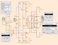
If you look at my diagram, you see the opamp output is split in 2 halves
and via foldback transistors fed to the output.
The blue lines show the path.
I have done SPICE for 100 W/8 Ohm 200W/4 Ohm with great results and performance.
OPA134 is good enough for this job.
I think you should have a look att this method if you are intesrested.
Regards Lineup
Op-Amps would be perfect to drive and control power amplifiers
if it wasn't for one thing:
- they work at too low voltage when it comes to higher power.
With the method I will show you, you can drive a power amp
even from an opamp working from +5/-5 Volt supply.
First, opamps can often put out 20-40 mA.
OPA134, which I have used for my SPICE, puts out 35-40 mA.
This is more than enough to drive one power output stage.
A triple Darlington needs no more than like 0.1 mA for plenty of Watt out.
One ordinary Darlington (driver + power transistor)
should do well on a couple of mA. Maybe max 5 mA in worst case.
This tells us, that there is no need to amplify the current from Op Amp.
We can let the output current, as it is, drive the power amplifier output.
If you look at my diagram, you see the opamp output is split in 2 halves
and via foldback transistors fed to the output.
The blue lines show the path.
I have done SPICE for 100 W/8 Ohm 200W/4 Ohm with great results and performance.
OPA134 is good enough for this job.
I think you should have a look att this method if you are intesrested.
Regards Lineup
Attachments

Hello!
Op-Amps would be perfect to drive and control power amplifiers
if it wasn't for one thing:
- they work at too low voltage when it comes to higher power.
With the method I will show you, you can drive a power amp
even from an opamp working from +5/-5 Volt supply.
First, opamps can often put out 20-40 mA.
OPA134, which I have used for my SPICE, puts out 35-40 mA.
This is more than enough to drive one power output stage.
A triple Darlington needs no more than like 0.1 mA for plenty of Watt out.
One ordinary Darlington (driver + power transistor)
should do well on a couple of mA. Maybe max 5 mA in worst case.
This tells us, that there is no need to amplify the current from Op Amp.
We can let the output current, as it is, drive the power amplifier output.
If you look at my diagram, you see the opamp output is split in 2 halves
and via foldback transistors fed to the output.
The blue lines show the path.
I have done SPICE for 100 W/8 Ohm 200W/4 Ohm with great results and performance.
OPA134 is good enough for this job.
I think you should have a look att this method if you are intesrested.
Regards Lineup
Nothing new about a power amp with more voltage gain after the VAS stage. Dan Meyer of SWTPC used that technique in the Universal Tiger back in the '70s. It did not use an IC opamp like yours but a discrete one. It had an annoying tendency to blow up.
G²
Hi There,
There are a number of variations of the op-amp-front-end circuit you designed in use out there in the real world. Carver uses a similar topology in most of their amps with a TL072 front-end, but the rest of the circuit is fairly complex implementing their class-G/low heat design. Alesis also uses a similar design using an NE5532, but the output stage is inverting, so the negative feedback is fed into the non-inverting input.
Attached is a simple op-amp/power amp circuit using an NE5532 and darlington outputs. It's very basic, but offers great sound and good stability into varying loads.
Paul
Attachments
also, lets not forget before Boulder went down the "cost no object" path of the current equipment, they made the 250 and 500 series power amps that were basically an op amp (albeit the 990 discrete op amp) driving an output stage with voltage gain.
mlloyd1
mlloyd1
- they work at too low voltage when it comes to higher power.
And designers worked around that decades ago. I don't see an amp design, merely a sketch of a basic topology that you can very often find from OpAmp driven amps. I've seen this scheme in dozens of guitar amps, for example. If you want something else, you could e.g. bootstrap the OpAmp's supply rails or just use the QSC-style scheme where the output stage itself additionally amplifies voltage.
Here is one of my latest simulations setup.
Some points:
Shows a run with 1Vrms input and 200 Watt out into 4 Ohm.
The output peak voltage is +-40 Vp. From 45V supply.
Distortion according to Fourier is 0.00066%
The AC current from op-amp shows 723 uA rms. Which is like +-1 mA peak!
For 200 Watt ....
The BC639/640 and MJE340/350 runs both 10 mA.
The output stage is biased in Class AB, like 75 mA per Power Device.
MJE15030/31 are drivers for 2 parallelled pairs MJL3281A/1302A
There are 3 Capacitors used to tailor the AC behavior and ensure stability.
C3 - can often be 5 - 22pF, depending on what transistors you use
C1, C2 - can be 100 - 680 pF to make a nice frequency/phase curve
What more can I say?
Only that I wish more people would try this.
Even in real life circuits. Because that is what counts.
Regards Lineup
* I have used andy_c own models for MJL3281A / MJL1302A
You can find them here:
Improved SPICE Models for MJL3281A and MJL1302A - Section 1
Attachments
Lineup out of my curiosity could you show us the THD spectrum of the sim, maybe at 10w, half power and full power.
Many musical fidelity amps from the '80s and 90's used a similar circuit but with output mosfets... then there is the Audio Analogue puccini et al... and various others including certain Fender guitar amps.... nothing new under the sun 😉
The biggest problem with this type of amp is that the added phase shift from driver and output stages can make them awkward to stabilize without ending up with a slow, limited bandwidth amp. Musical Fidelity actually rolled off the noise gain of the op-amp in order to re-gain stability margin.
The biggest problem with this type of amp is that the added phase shift from driver and output stages can make them awkward to stabilize without ending up with a slow, limited bandwidth amp. Musical Fidelity actually rolled off the noise gain of the op-amp in order to re-gain stability margin.
See aplication notes AN-272 at national.com, AN18 (and AN21) at linear.com, and AN-211 at analog.com.
While trying to realize a high power diamond buffer design, I stumbled upon this tread. It has inspired me to create a stable and working version a Op-amp driven power amp. The performance of it is extremely satisfying.
Thanks, lineup
Thanks, lineup
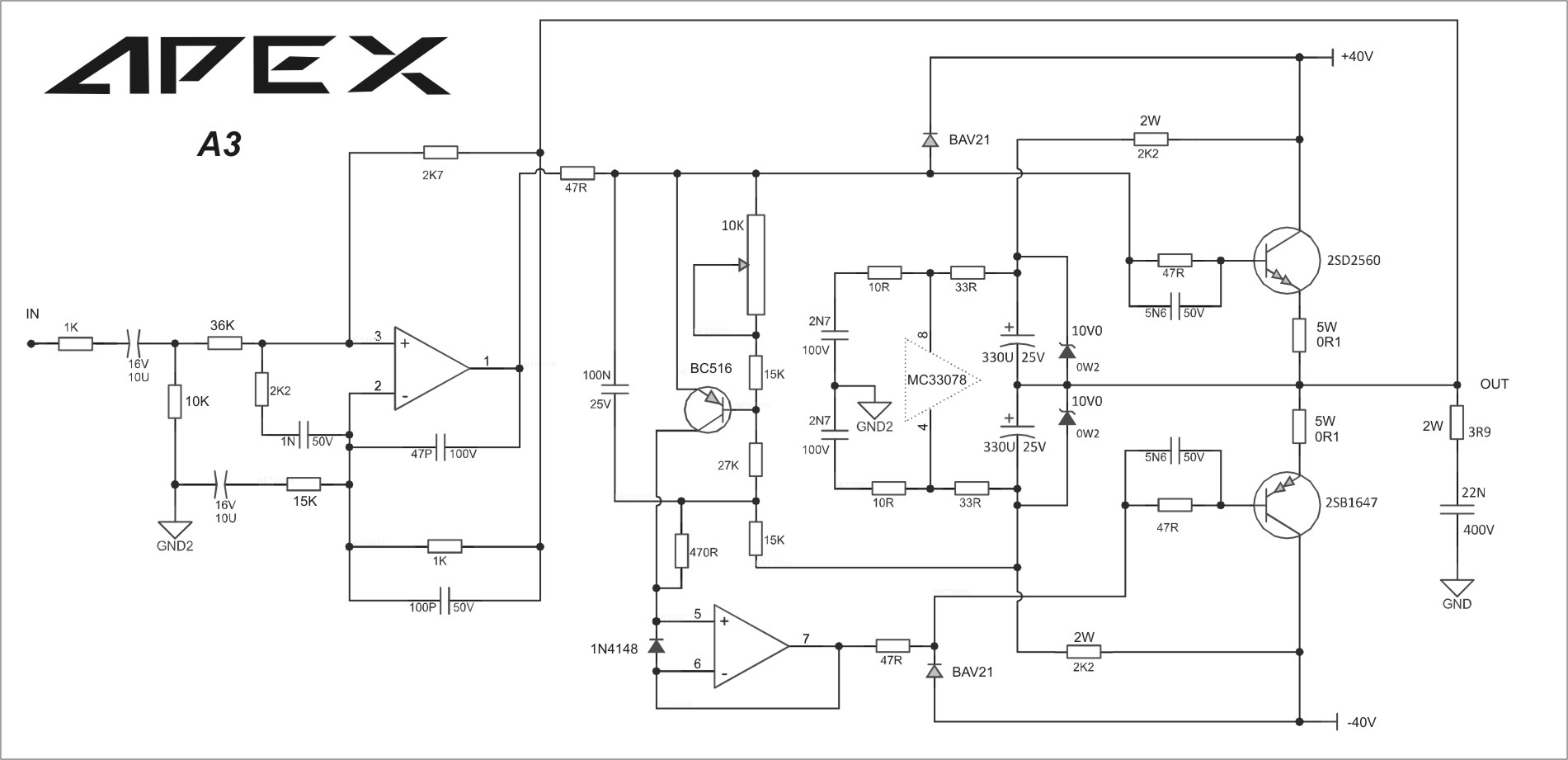
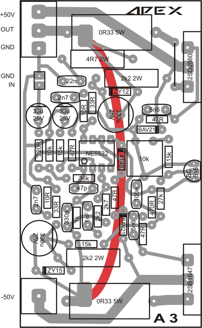
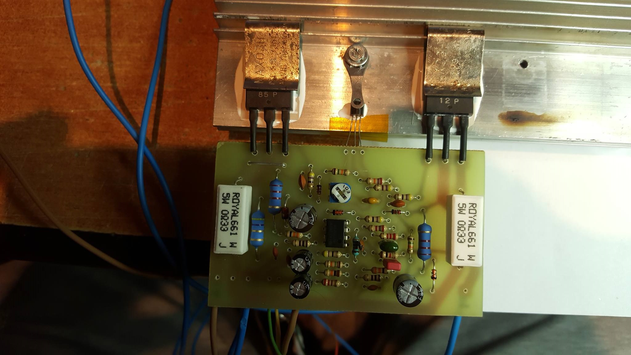
Not quite. I used similar circuit as suggested by Lineup. With some old parts from my parts bin and no capability of etching board, I made something like this.
Attachments


Around 1967 (49 years ago)--
Crown DC300, 200WPC, input uA739 (chip opamp) working on +/-10V power.
elektrotanya.com/crown_dc-300a_instruction_sch.pdf/download.html
There are dozens of other examples of boosted chips, some elegant, some messy.
Using a chip is a small short-cut in the long road to a good stable power amp. If you really understand the Power stages, the front end is a small (but important) detail. Looking at commercial designs it may come down to what saves a penny with the specific parts the company has standardized on.
Attachments

Oh, maybe I really don't understand the Power stages, but then I did went through a lot of failures before I completed this build, and I have learnt a lot from it.
I find OPA627 is relatively stable and well behave Op-amp. A well placed capacitor was all it took to stabilize the whole circuit.
I find OPA627 is relatively stable and well behave Op-amp. A well placed capacitor was all it took to stabilize the whole circuit.
There is a convenient benefit with op amps that saves a DIY builder the hassle of sourcing NOS or obsolete thru-hole monolithic pairs, sorting a bag of low noise TO92s for a fair match or making awkward thermal coupling arrangements on the PCB. With JFET inputs, its a no-brainer. For the price and convenience of using an opamp from the spare parts bin, you can be on your way to a high performance front end, FWIW.
At least it's a good way to find out what a good match can do for/to your audio 😉
At least it's a good way to find out what a good match can do for/to your audio 😉
Look this schematic ( Bose B1800 serie III, a OEM power amplifier from the German brand "Daub" )
What's with Bose devaluing good amps by sticking their name on it? They rebadged the T1500 and T2000 from MC2, calling it a B1500 and B2000 as well. I find it a little bit strange that both Bose and Quested (maker of very high end and extremely well-regarded studio monitors) rebranded the same amps.
- Home
- Amplifiers
- Solid State
- Op Amp (OPA134) driven Power Amplifier