I want to make a better sine wave than the below circuit produces. I know very little about OP amp design.... a capacitor or an inductor somewhere, or a whole different circuit? Or chip? Frequency range and amplitude are fine, but I can hear a "slapping" that I think are the points on the wave? Thanks!
Attachments

Hi, You may find this interesting. Frequency is adjusted by change of the R part of the C circuit.
http://www.ti.com/sc/docs/apps/msp/journal/aug2000/aug_07.pdf
http://www.ti.com/sc/docs/apps/msp/journal/aug2000/aug_07.pdf
Thanks, but I've already been changing the frequency with the C off pin 2. I need to smooth out the wave.....

That's the point: your circuit by design doesn't make a sine wave. If you really want something that comes close to a sine wave, you need to throw away your circuit and build something else, for example one of those TI circuits (though some of them don't have a well-defined amplitude).
On the other hand, if you just want a smooth waveform without sharp corners, it may be sufficient to just add a capacitor from pin 5 to ground. Try something of the order of 1 uF, depending on how smooth it needs to be.
On the other hand, if you just want a smooth waveform without sharp corners, it may be sufficient to just add a capacitor from pin 5 to ground. Try something of the order of 1 uF, depending on how smooth it needs to be.
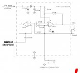
You need something like this. 😉
For low Zout add THS4031 buffer.
Looking at the original circuit, I think the intended frequency is about 1 Hz, which is somewhat unpractical for an LC oscillator.
No problem to get very stable 4,7 mH, 10 mH, ... 100 mH inductors these days.
No L saturation possible at gate current levels, very stable oscillator, H2 can be -50 dB when 2*C is trimmed.
No L saturation possible at gate current levels, very stable oscillator, H2 can be -50 dB when 2*C is trimmed.
OK, but how about the quality factor at 1 Hz? I would expect that the DC resistance ruins that, unless you have a really big core.
No problem 1 Hz, anyway this oscillator is more or less intended for fixed frequencies or switchable variants.
I want to make a better sine wave than the below circuit produces. I know very little about OP amp design.... a capacitor or an inductor somewhere, or a whole different circuit? Or chip? Frequency range and amplitude are fine, but I can hear a "slapping" that I think are the points on the wave? Thanks!
Perhaps the change in bias voltage is causing your amplifier to become unstable. It may be starting to oscillate on one of the peaks of the triangular waveform.
Marcel - You rock! I knew I went to the right forum.... ended up with an .047uF to keep amplitude (turns out it is a tradeoff). No more slap! (at the risk of being booted, it's for a tube amp - all I'm gonna say...). Needed some pure solid-state geekdom. Thanks again!
Attachments

Michael Bean has the correct solution...diode wave-shaping...frequency independent.
Used by signal generator IC's for many years.
A capacitor will filter harmonics but will change the amplitude with frequency...did you say tradeoff?
Used by signal generator IC's for many years.
A capacitor will filter harmonics but will change the amplitude with frequency...did you say tradeoff?
Thanks but I don't need a real sine wave, just a smooth cyclic modulation signal - which I now have. Don't want to make it too complicated and time consuming, but I do appreciate the information. A while back I needed to convert a square wave to a 0-5 VDC signal, and spent considerable time working with hex converters, VFOs and other devices. I have lots of other things I want to play with. Thanks again!
- Status
- Not open for further replies.
- Home
- Amplifiers
- Solid State
- OP Amp oscillator sine wave too sharp