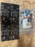
At the end of last year I was talking to Jim @6L6 about some project ideas, and the OPA1656 / BUF634A Headphone amp came up. I decided to make some prototype boards. I built up a board last night and the sound is nice!
Concepts considered for this prototype board included:
The schematic is attached.
Potential future concepts:
I have kitted up a few of these with SMD's pre-installed. 2 are spoken for, and 2 kits are available.
Giveaway:
1 OPA1656 / BUF634A Headphone Amplifier PROTOTYPE Kit.
Rules and conditions:
One entry per person (obvious, but worth saying).
If you're in the USA I'll pay shipping. If you're outside the USA, you will need to pay shipping. As long as USPS will ship to your country/address, you meet the criteria.
If you'll use the kit, sign up. You must be willing to build it up and comment on the sound within a month of receiving it
How it'll work:
To enter, just copy the list of entrants, paste into a new comment, add your DIYA username to the bottom of that list and post. In 48 hours or so, I'll make a comment saying that entries are closed. I'll take the final list of entrants, paste them into an online randomizer, and the name that appears in the top 2 positions will be the winners.
From there, that person simply needs to PM me their mailing address and I'll get them posted.
All parts are included to build it up EXCEPT for the 3-position disconnect block. I have included 2 "pigtails" for 9V batteries, so you could easily start with 2 9V batteries.
Concepts considered for this prototype board included:
- Make it 100mm wide to slide into a Hammond chassis. PCB is 100mm x 50mm
- Keep it simple
- Start with the datasheet schematic - the good engineers at TI know what they're doing.
- I wanted to dabble with Crossfeed, too. I made some separate boards for trying those.
- Install some sockets to allow flexibility to play with swapping gain resistors and bandwidth resistors.
The schematic is attached.
Potential future concepts:
- build it with a regulated power supply on board including a transformer.
- include a crossfeed circuit with a bypass/enable switch
- make a tiny version to add to a preamp
I have kitted up a few of these with SMD's pre-installed. 2 are spoken for, and 2 kits are available.
Giveaway:
1 OPA1656 / BUF634A Headphone Amplifier PROTOTYPE Kit.
Rules and conditions:
One entry per person (obvious, but worth saying).
If you're in the USA I'll pay shipping. If you're outside the USA, you will need to pay shipping. As long as USPS will ship to your country/address, you meet the criteria.
If you'll use the kit, sign up. You must be willing to build it up and comment on the sound within a month of receiving it
How it'll work:
To enter, just copy the list of entrants, paste into a new comment, add your DIYA username to the bottom of that list and post. In 48 hours or so, I'll make a comment saying that entries are closed. I'll take the final list of entrants, paste them into an online randomizer, and the name that appears in the top 2 positions will be the winners.
From there, that person simply needs to PM me their mailing address and I'll get them posted.
All parts are included to build it up EXCEPT for the 3-position disconnect block. I have included 2 "pigtails" for 9V batteries, so you could easily start with 2 9V batteries.
Attachments


Update #1. I found some 3 position connectors. They’re going in the kits.
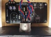
Update #2: I put this into a Hammond chassis with a FlexReg power supply board set for +/- 12v. What’s a FlexReg? I’m glad you asked. It’s a new board I did that has an on board transformer, CRCRC pre filter and then regulators and caps. It’s a FlexReg because you can choose fixed regulators (e.g. 7812 & 7912) or variable 317/337. I’ll make a separate thread for this board. For the record, the sound is quite nice on my Sennheisers.
Update #3: I’ll include a bare FlexReg board with the amp kit.
Drawing time is extended 1 day.
Attachments
-
 C038F79F-8C25-408A-A7C6-A2D74B688D06.jpeg393.5 KB · Views: 183
 -
 6D78A4CA-8C21-4ACD-8B2A-8ACA3FF2D13E.jpeg483.9 KB · Views: 252
 -
 961BD994-5D9C-4F26-9233-409C209F18ED.jpeg669.7 KB · Views: 237
 -
 EC94E70C-64B9-4E32-9472-DD379CFF0D60.jpeg432.3 KB · Views: 227
 -
 36076346-9C62-48C7-9D9F-37492DBF3260.jpeg557.8 KB · Views: 189
Dieter Geissel
DontHertzMe
anibal
mefistofelez
Keetesyflush
analogdiy
RogerGustavsson
grufti
dill3000
DontHertzMe
anibal
mefistofelez
Keetesyflush
analogdiy
RogerGustavsson
grufti
dill3000
Thanks for participating!!!
Winners - please send me a PM with your email an shipping info.
Winners - please send me a PM with your email an shipping info.
- anibal - WINNER #1
- mefistofelez WINNER #2
- RogerGustavsson
- analogdiy
- Dieter Geissel
- dill3000
- grufti
- DontHertzMe
- Keetesyflush
Congrats to the winners! I'm taking both packages to the post office now. I look forward to your feedback once you've had the opportunity to build. Let's see where this one goes. Standalone board to add to preamps? All-in-one with power supply? Add some crossfeed? Time will tell! When the next rev comes out I'll figure out a special way to involve all the Raffle entrants above in some form or fashion.
Hi rhthatcher,
as one of the lucky winners (albeit only at second place 😀), I would vote for a cross-feed add on first.
The "all-in-one with power supply" might not be needed because (i) it appears that people are passionate about the "appropriate" power supply, (ii) you already provided a solution, and (iii) the low power requirement lends itself to battery power.
I cannot comment of the "Standalone board to add to preamps" since I do not understand the meaning of the clause.
Kindest regards,
M
P.S. I was tempted to write that my opinion is worth what you paid for it, but since the kit has a value, which exceeds the value of my opinion, I abstained.
M
as one of the lucky winners (albeit only at second place 😀), I would vote for a cross-feed add on first.
The "all-in-one with power supply" might not be needed because (i) it appears that people are passionate about the "appropriate" power supply, (ii) you already provided a solution, and (iii) the low power requirement lends itself to battery power.
I cannot comment of the "Standalone board to add to preamps" since I do not understand the meaning of the clause.
Kindest regards,
M
P.S. I was tempted to write that my opinion is worth what you paid for it, but since the kit has a value, which exceeds the value of my opinion, I abstained.
Greetings all,
to satisfy Randy's stipulation:
Modifications:
As you will be able to ascertain from the attache pictures, I have made several modifications. These are not necessary, they reflect my associated equipment, environment, and/or building practices.
1. I have made provision for adding resistors between the output of the OPA1656 and the input of the BUF634A. Although the specification sheet notes that such resistors are not necessary for stability when the BUF634A is operated in the wide-band mode, which I am using, eventually I may decide to limit the band-width and thus current drawn and perhaps have stability issues. And, it is always better to have an option than not.
The modification was not difficult, the soldering mask does not appear to be of high quality, so it was easy to use X-acto knife, scrape the mask and cut the traces. I am using surface mount resistors which come in 0 Ohms.
2. I have omitted the RCA connectors and the potentiometer. Regarding the RCA I have not yet decided on the final mechanical assembly (what you see in the picture is my test fixture); furthermore, I do not like RCA, so I will probably use different connectors. Regarding the potentiometer, my source is digital and so is volume and balance control.
3. I have further omitted the coupling capacitors (C4, C8) since mu source is already AC coupled. Instead I used the footprint for installing resistors, which with an added capacitor in parallel with R4, R6 comprise an RF filter at about 1.2 MHz. I often listen in an RF lab, therefore, I consider such a filter mandatory.
4. I have also omitted the output connector (J3) because my headphones are wired for balanced operation, hence the XLR connector.
Build:
The kit I received contained all the necessary components, which are through-hole with the exception of the OPA1656 and the BUF634A, but these were already soldered on the board. All the parts fit perfectly (even the ones I omitted, I tried, see the OCD below), there is no need to adjust anything for fit.
However, I have matched all the resistors in the left and the right channel as well as the capacitors for the filter on a bridge, even accounting for the divider due to the filter resistor. It is completely unnecessary, but OCD is OCD.
Sound:
I will not describe the sound. First, our vocabulary is not well suited for describing the sound, consequently, the terms used are undefined and such arbitrary. E.g., what is "fast bass", "thin highs", etc?
Suffice to say that I am satisfied with the sound, which is not a surprise since I used to have an amplifier based on this architecture, a PCB of which has been destroyed by modifications, when I was experimenting with it.
Lastly, I want to express my gratitude to Randy for providing such a kit.
Kindest regards,
M
to satisfy Randy's stipulation:
here are some notes.If you'll use the kit, sign up. You must be willing to build it up and comment on the sound within a month of receiving it
Modifications:
As you will be able to ascertain from the attache pictures, I have made several modifications. These are not necessary, they reflect my associated equipment, environment, and/or building practices.
1. I have made provision for adding resistors between the output of the OPA1656 and the input of the BUF634A. Although the specification sheet notes that such resistors are not necessary for stability when the BUF634A is operated in the wide-band mode, which I am using, eventually I may decide to limit the band-width and thus current drawn and perhaps have stability issues. And, it is always better to have an option than not.
The modification was not difficult, the soldering mask does not appear to be of high quality, so it was easy to use X-acto knife, scrape the mask and cut the traces. I am using surface mount resistors which come in 0 Ohms.
2. I have omitted the RCA connectors and the potentiometer. Regarding the RCA I have not yet decided on the final mechanical assembly (what you see in the picture is my test fixture); furthermore, I do not like RCA, so I will probably use different connectors. Regarding the potentiometer, my source is digital and so is volume and balance control.
3. I have further omitted the coupling capacitors (C4, C8) since mu source is already AC coupled. Instead I used the footprint for installing resistors, which with an added capacitor in parallel with R4, R6 comprise an RF filter at about 1.2 MHz. I often listen in an RF lab, therefore, I consider such a filter mandatory.
4. I have also omitted the output connector (J3) because my headphones are wired for balanced operation, hence the XLR connector.
Build:
The kit I received contained all the necessary components, which are through-hole with the exception of the OPA1656 and the BUF634A, but these were already soldered on the board. All the parts fit perfectly (even the ones I omitted, I tried, see the OCD below), there is no need to adjust anything for fit.
However, I have matched all the resistors in the left and the right channel as well as the capacitors for the filter on a bridge, even accounting for the divider due to the filter resistor. It is completely unnecessary, but OCD is OCD.
Sound:
I will not describe the sound. First, our vocabulary is not well suited for describing the sound, consequently, the terms used are undefined and such arbitrary. E.g., what is "fast bass", "thin highs", etc?
Suffice to say that I am satisfied with the sound, which is not a surprise since I used to have an amplifier based on this architecture, a PCB of which has been destroyed by modifications, when I was experimenting with it.
Lastly, I want to express my gratitude to Randy for providing such a kit.
Kindest regards,
M
Attachments

Last edited:
- Home
- Amplifiers
- Headphone Systems
- OPA1656 / BUF634A Headphone Amplifier