Hi.
I have been building single supply opamp circuits for a while now with good results. Recently I have been asking myself a certain question pertaining to the virtual grouns scheme I always use. NOW, I know there are better wsys of doing this using buffers, regulators etc, but my question only relates to the resistor divider arrangement.
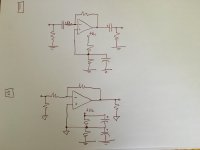
I have attached to schematics (sorry for the hand drawn sketch).
In "1" you have the virtual ground only connected to + of the opamp, and making use of input snd iutput capscitors to decouple the half supply. All IO's referenced to ground.
In "2" you have the virtual ground setup to represent 0V virtually. No input and output coupling caps.
Which arrangement is better? My common sense tells me that in 2, because the output load will be directly connected to the resistor devider, the load will make the virtual 0v point unstable due to it drawing current from here.
In 1 it seems as if the 1/2Vcc point is slightly "buffered" by the op amp.
Anything im missing?
Guess i would like to know the lesser if these two evils. ��
I have been building single supply opamp circuits for a while now with good results. Recently I have been asking myself a certain question pertaining to the virtual grouns scheme I always use. NOW, I know there are better wsys of doing this using buffers, regulators etc, but my question only relates to the resistor divider arrangement.
I have attached to schematics (sorry for the hand drawn sketch).
In "1" you have the virtual ground only connected to + of the opamp, and making use of input snd iutput capscitors to decouple the half supply. All IO's referenced to ground.
In "2" you have the virtual ground setup to represent 0V virtually. No input and output coupling caps.
Which arrangement is better? My common sense tells me that in 2, because the output load will be directly connected to the resistor devider, the load will make the virtual 0v point unstable due to it drawing current from here.
In 1 it seems as if the 1/2Vcc point is slightly "buffered" by the op amp.
Anything im missing?
Guess i would like to know the lesser if these two evils. ��
Attachments
Your second drawing is confusing because you use 2 different ground symbols, the triangle and the parallel lines one, and unless specifically said (you don't) both could be called ground ... yet they are 4.5V DC away from each other (if Vcc is 9V)
In fact, the top one is the classic one, since everything is referred to 1/2Vcc you need decoupling caps everywhere.
Still popular in pedals, because it's easy to use a single 9V battery and switch it with just a single contact, usually the pedal input or output jack, which acts as an SPST switch.
You can (and must) ground one end of the battery, usually the -V terminal, although grounding the +V one is also valid.
The second one simulates a split supply, you can't ground either end of the battery and need a DPST switch for it.
And don't use a ground symbol for the battery negative terminal, call it -1/2Vcc or -4.5V if using a 9V battery.
Of course the + terminal will be called +4.5V , not +9V , because it is not any more referred to ground.
Your still labelling it +Vcc as if it still were the full voltage and labelling the other end of the battery with a ground signal is confusing.
Last edited:
Your second drawing is confusing because you use 2 different ground symbols, the triangle and the parallel lines one, and unless specifically said (you don't) both could be called ground ... yet they are 4.5V DC away from each other (if Vcc is 9V)
In fact, the top one is the classic one, since everything is referred to 1/2Vcc you need decoupling caps everywhere.
Still popular in pedals, because it's easy to use a single 9V battery and switch it with just a single contact, usually the pedal input or output jack, which acts as an SPST switch.
You can (and must) ground one end of the battery, usually the -V terminal, although grounding the +V one is also valid.
The second one simulates a split supply, you can't ground either end of the battery and need a DPST switch for it.
And don't use a ground symbol for the battery negative terminal, call it -1/2Vcc or -4.5V if using a 9V battery.
Of course the + terminal will be called +4.5V , not +9V , because it is not any more referred to ground.
Your still labelling it +Vcc as if it still were the full voltage and labelling the other end of the battery with a ground signal is confusing.
You are right. I should have labelled the units in the second drawing as +V and -V. The 1/2V point know becomes 0V.
I would call 1. a single supply with AC coupling of the amplifier.
and 2. is dual polarity supply with DC coupling of the amplifier.
Coupling capacitors can be added to 2. if preferred, making it AC coupled at either the input, or the output, or both.
and 2. is dual polarity supply with DC coupling of the amplifier.
Coupling capacitors can be added to 2. if preferred, making it AC coupled at either the input, or the output, or both.

"1" is a classic time-proven AC-coupled single supply circuit.
"2" is a more cMoy-like virtual ground affair. Note that this one has bad PSRR as shown and would benefit from executing the VGND like "1" has - omit the top electrolytic, best replaced by a protection diode (in order to avoid input damage upon power-down), add a second 'lytic across +Vcc.
In "2", you can potentially save on a few parts - the input and output resistors to ground are not actually needed (an output series resistor to keep cable capacitance off would be a better idea). It does put a somewhat heavier load on the VGND, which has to absorb output load current, still not usually too much of a deal in a non-inverting circuit. Note that for low-impedance loads (say, a headphone driver), the VGND imposes a power bandwidth limit towards the low frequencies, as it's in series with the ground return. It's a bit like "1" with a common coupling cap for L and R in the ground return, like e.g. the Behringer HA400 amp appears to have, except that is a "standard" bandwidth limit.
- Status
- Not open for further replies.