Optimum Crossover
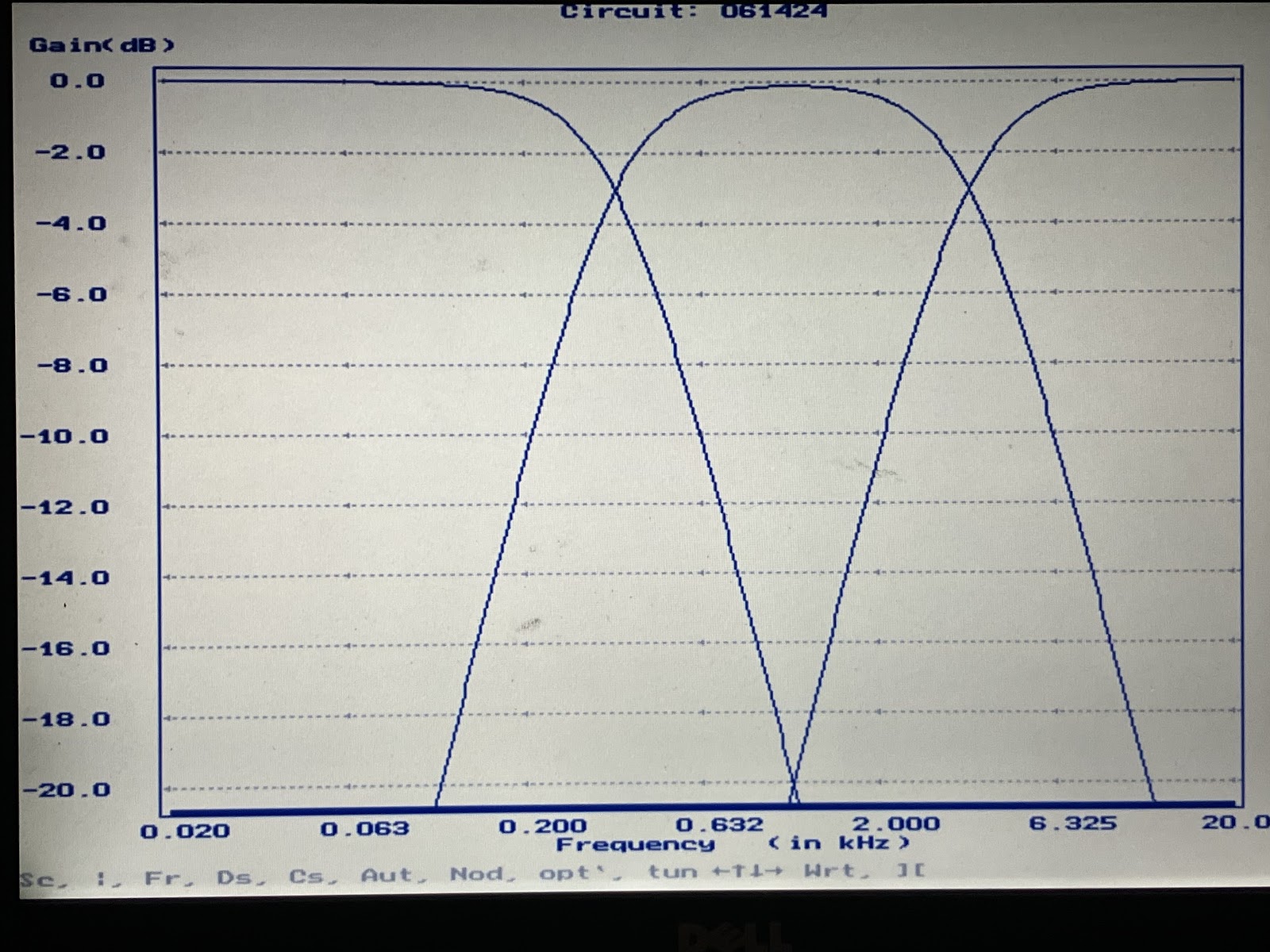
I have developed what I believe is an exceptional audio crossover. I have tested it theoretically using the circuit analysis program Nova-686. The frequency response is perfectly flat from 20 to 20 kHz.
I am inclined to believe that this may be the best possible passive, three-way crossover. However, I am open to feedback and would appreciate it if someone could review it and provide his opinion.
Crossover Characteristics
Crossover Frequencies
The frequencies chosen serve as a good starting point for the DIY builder.
20 Hz to 350 Hz.
350 Hz to 3500 Hz
3500 Hz to 20 kHz
Physical Limitations
Moving from the theoretical to the practical presents some challenges.
Audio drivers do not exhibit ideal impedances. This leads to non-flat frequency responses. However, Zobel networks can be employed to address this discrepancy.
It is difficult to go from a theoretical design to one using standard parts. However, this design achieves optimum performance using standard part values.
Schematic “Best Possible Passive Crossover”
(3-way 2nd order)
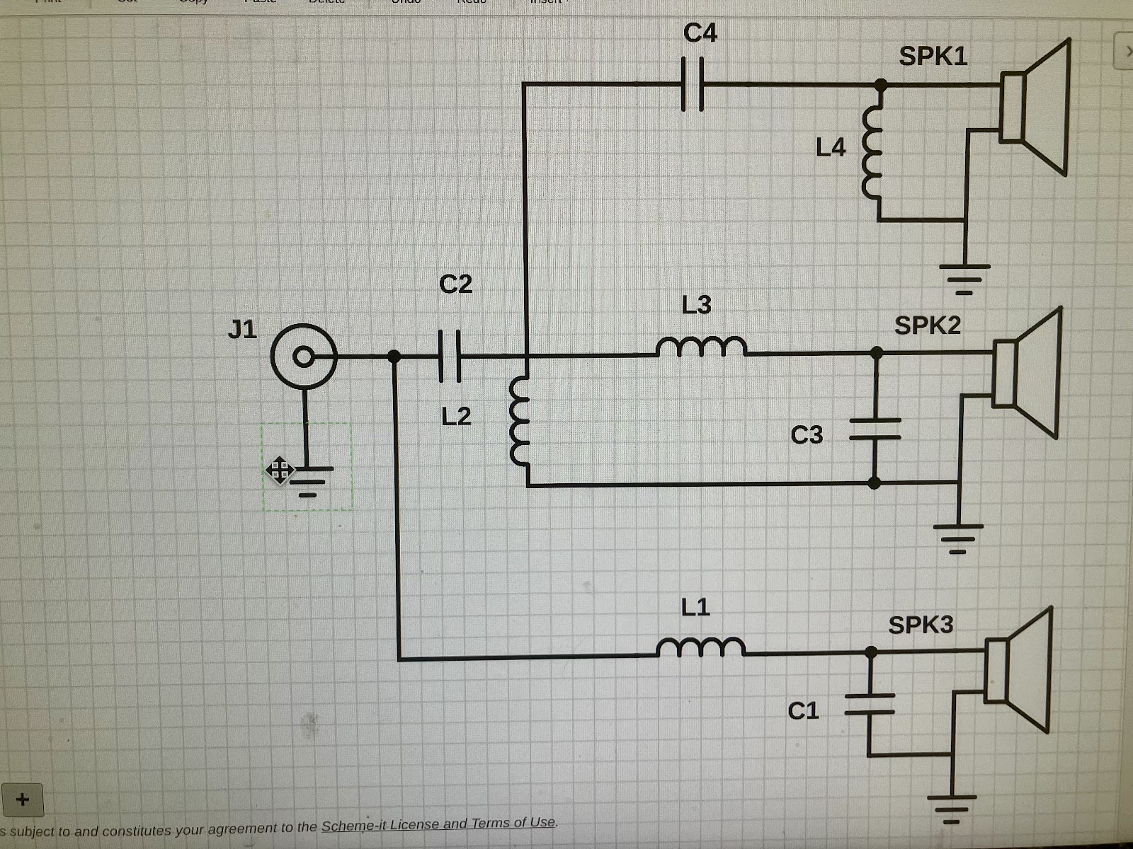
PS (The mid driver must be phase inverted.)
L1 = 5.0 mH C1 = 39 uF
L2 = 5.0 mH C2 = 39 uF
L3 = 0.5 mH C3 = 3.9 uF
L4 = 0.5 mH C4 = 3.9 uF
Frequency Response
Copyright 2024
Robert Stanton
I have developed what I believe is an exceptional audio crossover. I have tested it theoretically using the circuit analysis program Nova-686. The frequency response is perfectly flat from 20 to 20 kHz.
I am inclined to believe that this may be the best possible passive, three-way crossover. However, I am open to feedback and would appreciate it if someone could review it and provide his opinion.
Crossover Characteristics
- Flat frequency response. +/- 0.01 dB, 20 Hz to 20 kHz.
- The input impedance is a constant at 8 Ohms
- Good square wave response..
- Group delay, 670 usec max.
- Consists of only four capacitors and four inductors. (no resistors).
Crossover Frequencies
The frequencies chosen serve as a good starting point for the DIY builder.
20 Hz to 350 Hz.
350 Hz to 3500 Hz
3500 Hz to 20 kHz
Physical Limitations
Moving from the theoretical to the practical presents some challenges.
Audio drivers do not exhibit ideal impedances. This leads to non-flat frequency responses. However, Zobel networks can be employed to address this discrepancy.
It is difficult to go from a theoretical design to one using standard parts. However, this design achieves optimum performance using standard part values.
Schematic “Best Possible Passive Crossover”
(3-way 2nd order)
PS (The mid driver must be phase inverted.)
L1 = 5.0 mH C1 = 39 uF
L2 = 5.0 mH C2 = 39 uF
L3 = 0.5 mH C3 = 3.9 uF
L4 = 0.5 mH C4 = 3.9 uF
Frequency Response
Copyright 2024
Robert Stanton
You have made what is commonly referred to as a textbook crossover. Kudos for your progress thus far. There are four factors that will impact the usefulness your filter: driver impedance (this you have identified), driver sensitivity, in-situ driver frequency response and driver useable bandwidth (distortion profile and directivity).
The problem with textbook crossovers is that it assumes that all the extra factors mentioned above are ideal. Dedicated loudspeaker design softwares typically have utilities that account for all the above-mentioned parameters and enable the user to assess the final product.
The challenge is getting close to the ideal of our chosen crossover topology (as you have demonstrated with ideal conditions) using real-world measured data.
I recommend the tools REW (Room EQ Wizard) for acoustic and electrical measurement and VituixCAD for crossover design. Both are freeware.

Moving from the theoretical to the practical presents some challenges
you make no reference to the drivers responses, the drivers are also filters.
the combination of the crossover and driver gives the resultant acoustic response.
the resultant acoustic response is the one that matters, not the crossover.
Just for fun I put your design into VituixCAD and your filter is what you describe, however even with perfect 8 ohm concentric drivers the response isn't close to what you described.


I then made some adjustments and spaced the perfect drivers with more realistic layout and adjusted the component values. I also needed to add some padding resistors to adjust the tweeter and mid levels to compensate for the boost caused by the band pass filter. This got closer to the flat response you where trying to get. I did did not bother to model any diffraction to compensate for baffle step. Finally as others have said everything goes out the window when real drivers are used.
Edit: I set the the inductors resistance to near zero in an attempt to simulate the optimum crossover.
From a quick gander, the stated values in post one match standard 2nd order electrical Butterworth values for the stated frequencies & a static 8ohm impedance load rounded to the nearest easily available components.
Your computer program's frequency response curve is the result of summing the three output voltages as vectors. I initially utilized this analysis method but later decided against it.
When you sum the three output voltages from a crossover system, the outcome is a dimensionless value. This is due to the fact that the three voltages being combined are not physically linked in series; instead, they represent the magnitudes and phases of individual isolated signals.
Subsequently, these signals are merged by the three drivers into three distinct pressure waves, each following its independent path.
In my opinion, a flat audio system is characterized by a consistent power output measured in Watts, across the frequency range of 20 Hz to 20 kHz.
Two incoherent sources of equal loudness combine to a +3 dB increase, while two coherent sources of equal loudness combine to a +6 dB increase.
Connecting all drivers to the same voltage source as shown in the original post will generally be coherent. (appropriate polarity counts)
Note that when a 3rd driver is rolled off 20 dB or more relative to the two primary drivers in the crossover, its contribution is fairly insignificant in the total summation.
Calculator here -
https://sengpielaudio.com/calculator-leveladding.htm
As others have stated, non-ideal behavior of impedance, frequency response (spl), and acoustic phase, etc. play a big part in the overall output sound. Haven't encountered any ideal drivers in my experience. At least in my budget. 😉
I read your response many times and if I actually understand what you are saying then I disagree.Your computer program's frequency response curve is the result of summing the three output voltages as vectors. I initially utilized this analysis method but later decided against it.
When you sum the three output voltages from a crossover system, the outcome is a dimensionless value. This is due to the fact that the three voltages being combined are not physically linked in series; instead, they represent the magnitudes and phases of individual isolated signals.
Subsequently, these signals are merged by the three drivers into three distinct pressure waves, each following its independent path.
In my opinion, a flat audio system is characterized by a consistent power output measured in Watts, across the frequency range of 20 Hz to 20 kHz.
Your first sentence you dismiss the VituixCAD modeling software's use of vector math to predict the output LCR circuit's response to an A/C input signal. In your second sentence you claim that the outputs of the LC filters are dimensionless values and then immediately describe these signals as having phase. Phase is the relationship between the output current and voltage and is used to calculate output power. I know it has been a long tome since I took 3 semesters of A/C circuits, but at that time vector math was the only way to calculate the output of an LCR circuit.
As stated by others earlier the crossover you present does not yield a flat audio system, there are 3db peaks at each crossover point. I'm not saying the in room response might not be fine, but it won't be flat.
Right, let's be honest here. As already noted, this 'optimum crossover' is nothing more than standard electrical 2nd order Butterworth high & low pass values for the stated frequencies (a point the OP carefully avoids mentioning, despite claiming 'copyright') & a static 8ohm load. As a Butterworth filter it has a constant (flat) power response & amplitude response either sums +3dB or with a deep null at the crossover frequencies depending on polarity. As many have also already said, this is all fairly worthless anyway given the typically non-flat FR of most drive units, their non-flat impedance loads and the fact that the vast majority are not coincident.
If the SPK1 circuit truly connects at the red circle, then it's actually 4th order, electrically, isn't it?

Looks like 24db per octave up to 300hz. Not sure how that can happen without a 4th order circuit. What am I missing?
.png")
It must be connected at the Red circle otherwise SPK1 doesn't receive any signal.If the SPK1 circuit truly connects at the red circle, then it's actually 4th order, electrically, isn't it?
View attachment 1326867
Simple answer: because the tweeter branch IS a fourth order highpass below 300 Hz !Looks like 24db per octave up to 300hz. Not sure how that can happen without a 4th order circuit. What am I missing?
Regards
Charles
Yeah, that's what happens when you connect a 2nd order Butterworth HP leg like that. Irrelevant to the response given the transition frequencies though.
Merely pointing out that this deviation from the textbook 2nd order Butterworth crossover does indeed lead to a constant 8 ohm load.
.png")
- Home
- Loudspeakers
- Multi-Way
- Optimum Crossover