Hello,
I am going to recap the P.S. of a (very old > 30 years) DAC, and its linear PS capacitors are 9x2200µF 50V Nichicon VX 85°C.
My first choice as designer would be to use low ESR 105°C capacitors, such as the Nichicon PM or Cornell Dubillier 228KXM050M, just to mention some currently in stock at Mouser.
But some people around argue that the Nichicon KW 85°C would "sound better"... Although I have also eared various positive feedbacks regarding the KW, I still believe that it is better to use the first I mentioned in this particular circuit location.
I would just like to have your viewpoint regarding what would be "the best" in this particular location: in a inear P.S. just after the bridge rectifiers...
Thank you for your viewpoint
Capacitors is the most flammable topic on the forum. 
My perspective is:
"Audio grade" capacitors MAY BE a good choice for SIGNAL PATH if compared to conventional wet electrolytics.
For power rails, only at some specific points the DAC needs high capacitance (ak4490 recommends up to 2200uF in VREF).
But in stages of rectification, reservoir of energy... any series of reliable brands with sufficient specifications for the project such as ripple current, will deliver the same result.
What intrigues me most about this is that no information is presented in the datasheet of these series.
regards.
Yes I know ! That is why I ask the question from an engineer viewpoint only...Capacitors is the most flammable topic on the forum
I fully agree with you.
In addition when you say:
I have learned to use 105°C / Low ESR / High ripple current capacitors in this specific rectification area, not audio grade caps.But in stages of rectification, reservoir of energy... any series of reliable brands with sufficient specifications for the project such as ripple current, will deliver the same result.
Of course I will always use Audio caps in the signal path, but in the P.S. rectification area....
Knowing how high is that high ripple would be a bonus...If you have enough space you can always parallel more caps for lower esr..Look for long life under considetable stress, and long shelf life .Some 105 caps are specified for 2 amps surge while some 85 caps are specd for 6 amps...thus you know they are actually identical in specs.
Lol...what a dac... I mean what an amp!
9x 2200 50v amp for certainly a 12 VAC secondary. Good Nichicon VX...the esr should be low enough yet with 9 in //...some leakage...measurable. Give them 10 years more 🙂. But if you see bumped top or electrolyt leaks.
9x 2200 50v amp for certainly a 12 VAC secondary. Good Nichicon VX...the esr should be low enough yet with 9 in //...some leakage...measurable. Give them 10 years more 🙂. But if you see bumped top or electrolyt leaks.
I agree with your choice to prefer low ESR and long-life capacitors in a linear power supply, over “audio grade” or boutique variety.
However, depending on how PS was made, it could be bad choice to use low ESR capacitors for reservoir capacitors, first ones after the rectifier. If their ESR is lower than what original capacitors had by design, charging pulses will be shorter in duration but higher in value, producing EMI spikes that could propagate through ground planes to analog section. For that reason, some PS have small resistor between rectifier diodes and first capacitor. No problem to use low ESR caps after resistor if there is a CRC chain.
Regarding capacitors sound, my opinion is that only PS capacitors that are in the direct signal path, can affect sound by small measure through their specific ESR & ESL properties.
There should be some voltage regulators after reservoir capacitors. If they have large capacitors at their output as well, then it is possible that output capacitors bank could dominate PS output impedance at higher frequencies and output capacitors choice could affect resulting sound. Yes, they are in signal path as AC current through any load must close its circle from one pole to another through power supply and if capacitor AC impedance is close to regulator impedance, at least part of AC current will go through PS output capacitor.
Disclaimer: changing PS capacitors, I don’t find any difference in sound. Though, I use extremely low output impedance voltage regulators. 🙂
YMMV

Interesting, as are the other replies above.However, depending on how PS was made, it could be bad choice to use low ESR capacitors for reservoir capacitors, first ones after the rectifier. If their ESR is lower than what original capacitors had by design, charging pulses will be shorter in duration but higher in value, producing EMI spikes that could propagate through ground planes to analog section. For that reason, some PS have small resistor between rectifier diodes and first capacitor. No problem to use low ESR caps after resistor if there is a CRC chain.
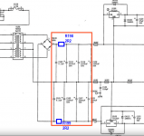
I have attached an extract of the Power Supply schematics, that goes from the bridge to the voltage regulators: I don't see any resistor between the rectifier bridge and the reservoir capacitors that are inside the red rectangle.
Does it help you to determine if low ESR caps are the way to go, or if I should stay to some general purpose 85°C capacitors ?
Attachments

Hi,I had replaced some Nichicon VX (M) in old decks and I was positively surprised to measure low ESR as much as in modern types and nominal uF values in them after 35+ years since the equipment was put together.
Have you measured the leakage as well ?
Does it help you to determine if low ESR caps are the way to go, or if I should stay to some general purpose 85°C capacitors ?
Nichicon declared VX caps as standard series, so not low ESR. As actual ESR is nowhere specified, we can’t make competent decision. Salas measured them as “low ESR as much as in modern types”. Most modern 2200 uF/50V capacitors are low ESR, even down to 16 mΩ. If someone doesn’t chime in with actual measured VX capacitor ESR, it would be on the safe side to avoid those with extremely low ESR.
As you are determined to thoroughly overhaul some old DAC, you could gain more with planned rectifier bridge replacement, if done in a more elaborate way. Small additional piggy-back PCB, connected where rectifier bridge was, could carry positions for a snubber (2 capacitors + 1 resistor) and optional position for 0.1 – 0.22 Ω resistor. Adding snubber, will bring measurably les noise, though I’m still not convinced that it will result in any audible improvement. Component values for snubber must be measured with Quasimodo test-jig. Quasimodo
With optional resistor, any low ESR/long life capacitors can be used without increased charging pulses and corresponding EMI.
The transformer appears (Figure 1) to be an AMVECO 70063K whose datasheet is available online. It's rated 25 volt-amperes, so each of the 15VAC RMS secondaries delivers 0.833 amperes maximum. Plugging that into the capacitor equation with C = 3 x 2200uF (Figure 2) we find that the peak-to-trough magnitude of the ripple voltage is 1.26V in the worst case.
In the worst case when Imax is flowing, and the mains is 10% below normal, and the rectifier voltage drop is 1.0V, the trough of the ripple voltage is 16.8 volts. That's the input to the LM7812 regulator ICs.
The output of the regulators, in the worst case, is 12.6V. So the input-to-output voltage is 16.8 - 12.6 = 4.2 volts in the worst case. Datasheet spec for min input-to-output voltage is 2.0 volts -- so you've got an excess of 2.2 volts that you can "squander", reducing the magnitude of the current pulses which charge and discharge the 2200uF filter capacitors. This reduces their self-heating and increases their lifetime.
One way to "squander" 2.2 volts, is to install a series resistor, which drops 2.2 volts when the worst case current (0.833 amps) is flowing. That resistor's value is (2.2V / 0.833A) = 2.6 ohms. Round down to the nearest E6 standard value: 2.2 ohms. See R198 and R199 in Figure 2.
Those resistors need to be rated for 5 watts, since they carry 0.833 amperes. When ordering resistors from Mouser, I myself would also order 1.5 ohms (5W) and 3.3 ohms (5W) for lab experimentation. Hook it up to the oscilloscope, study the traces, and ask: am I okay with these waveforms? If not, make a change.
_
Attachments

Luckily I have kept little few. Nichicon VX (M) 4.7uF 50V 85C used. Pulled from a 35 years old cassette deck. Its 100kHz ESR on DER EE DE-5000 LCR Meter reads 0.573Ω. Elna Silmic II 4.7uF 35V bought six months ago from Mouser. Unused. 1.667Ω ESR. On the same meter with the same measuring conditions.Nichicon declared VX caps as standard series, so not low ESR. As actual ESR is nowhere specified, we can’t make competent decision. Salas measured them as “low ESR as much as in modern types”.
Attachments


No, but I can report DF 0.015 100Hz (1.5%) on the above VX cap. Also DF 0.057 at 1kHz.Hi,
Have you measured the leakage as well ?
PSUD2 is our friend (on condition we have required data). 🙂
Simulation reveals that this small transformer's secondary resistance is great equalizer of max. current peaks with any ESR. Assuming 1 Ω secondary DC resistance and 200 or 20 mΩ ESR per capacitor, reveals that peak difference is only 0.2 A or 2.4 vs. 2.6 A. Adding 2.2 Ω resistor reduces peaks to 1.7 A.

Simulation reveals that this small transformer's secondary resistance is great equalizer of max. current peaks with any ESR. Assuming 1 Ω secondary DC resistance and 200 or 20 mΩ ESR per capacitor, reveals that peak difference is only 0.2 A or 2.4 vs. 2.6 A. Adding 2.2 Ω resistor reduces peaks to 1.7 A.
IMO, ESR is totally irrelevant in 50/60 Hz power supplies. It's also an annoying number to work with, being highly frequency sensitive. Unless you're a SMPS designer it's probably not the number you should be thinking about. Dissipation factor is the number to look at, measured at 120 Hz, but any decent cap of sufficient value will automatically have a low enough dissipation factor.
{as tombo56 said 2 hours ago while I lunched} That power transformer is liable to have an Ohm or so of ESR, and that is sure part of the circuit.I don't see any resistor between the rectifier bridge and the reservoir capacitors that are inside the red rectangle.
Just did for your information. Same VX (M) 4.7uF 50V old used cap from my previous post pictures. Measures 0.043μΑ leakage at rated DC voltage after two minutes. The new unused 4.7uF 35V Silmic II measures 0.14μA at rated DC voltage after two minutes. Room temperature 26C in both occasions. I used mV meter across 1K feed resistor for accuracy.Hi,
Have you measured the leakage as well ?
There should be some voltage regulators after reservoir capacitors. If they have large capacitors at their output as well, then it is possible that output capacitors bank could dominate PS output impedance at higher frequencies and output capacitors choice could affect resulting sound. Yes, they are in signal path as AC current through any load must close its circle from one pole to another through power supply and if capacitor AC impedance is close to regulator impedance, at least part of AC current will go through PS output capacitor.
This is a very interesting point, PS rails after regulators.
I agree that it can generate sound differences, but they are usually 47uF/100uF capacitances...
Why not use tantalum or solid polymer capacitors? 🤔
Why would the "old" wet electrolytics have better performance?
It seems that folks these days share more personal preference than experience. 🙁
Why this 0.1 uF at the secondary output in first place ? Is it to reduce the high frequency noise coming from the main to spread into the circuitry?
Could it be no better rigth on this reg ic pins between the input and the gnd ? Then the 2r2 splited in lower values for a CRCRC knowing the low VA of the traffo and what a standalone 3300 uF is able to do (around 2.5 A ?) ?
Could it be no better rigth on this reg ic pins between the input and the gnd ? Then the 2r2 splited in lower values for a CRCRC knowing the low VA of the traffo and what a standalone 3300 uF is able to do (around 2.5 A ?) ?
- Home
- Design & Build
- Parts
- P.S. caps: Nichicon PM vs Nichicon KW