Crossovers were delivered wrong on the factory speakers. A quick fix involves just a few simple steps. Your jaw will drop when you hear the difference!
1. Open rear cover plate on speaker. 4 screws.
2. Pull out gently and note the crossover is attached.
3. Solder a shorting jumper over the sand resistor 3R3.
4. Cut thin red solid wire and solder to Heavy red wire's solder pad.
These actions do two things:
1. Over-ride the attenuation blocking action of the 3.3 ohm resistor, thus allowing the mid tweeter to open up.
2. Bypass the awful 1.8uf bipolar electrolytic capacitor that is in line with the ribbon tweeter. The ribbon does not need the cap at all and now it is directly across the primary speaker leads.
The Philips MCD-908 stereo system came out in 2007.
What you will notice when you re-power your speakers is a bright and full spectrum of sonic harmony. Especially in the ribbon tweeter which is now operating as intended!
Last edited:
Ribbon tweeters don't usually appreciate being connected to DC, despite the transformer. Removing the 1.8uF blocking capacitor might be a very bad idea. the 3.3R could be anywhere, but I suspect something just got louder.
Decca Kelly ribbon schematic below.
Without a schematic, frankly, your ideas don't inspire confidence. 🙂
Decca Kelly ribbon schematic below.
Without a schematic, frankly, your ideas don't inspire confidence. 🙂
Attachments


The 3R3 in-line resistor for the mid-tweeter was prescribed, I believe, by formula to reduce the sensitivity. I do have a diagram of the circuit which I made before the change.
About the capacitor for the ribbon tweeter. My issue is the fact that a bi-polar electrolytic capacitor was used here. I now feel perhaps polypropylene capacitor may have been a better choice.
Other remarks:
Perhaps the designer may have been going by data only when determining the values of these components, rather than the test and trial method to verify that "this is what you really get with these values and these components."
My son is coming over later this week to do some sonic tests and review what sense, if any there may be of this. Yet I do think this is a vast improvement, and would appreciate further comment from all. This project is by no means over, and it is worth going further to really understand how the mechanisms are working to provide the best possible solution.
Thanks!

TBH, most of us started this fun hobby with some cheapie pair of speakers we wanted to try and improve.
These look like fun. But it's actually quite hard to distinguish cheapie NP electrolytics from polypropylenes aside from the polypropylenes sounding brighter.
But read my lips. Tweeters don't appreciate DC. That 1.8uF is protecting it from excessive current at low frequencies.
A sort of ribbon supertweeter is quite a fun idea, and can have effects on impedance as much as frequency response.
TBH, I'd look at some serious designs here:
SEAS 5INCH
Different league from cheap simple commercial designs. Enjoy. 🙂
I will take your advice right away and protect the ribbon. But I will use a poly. 🙂
Thanks much for your help!
Thanks much for your help!
I can give you some further tips.
Removing that 3.3R reduces impedance to a dangerously low 2 ohms. Your amp may fry. 😱
Your schematic doesn't make sense to me. The series coil should come after the shunt coil in the midpass. If that is what it is.
It's a 4 ohm 100mm bass, I would guess. A NP electrolytic in the bass shunt helps by adding a little resistance. Tames a tendency to peak at crossover. Hence is a FEATURE, rather than a fault. 😀
Attachments


I agree. But that diagram I made is truly what what the factory did. I went over it and again and could not fathom it. I agree it does not even look correct, but somehow it works.
Status:
The cap & inductor on the woofer is not changed.
The design on the mid-tweet is restored to original.
The errant electrolytic capacitor on the ribbon is changed to a higher voltage polypropylene type.
Details:
OK I did some more testing and I put the 3R3 resistor back in to restore the the design, sound level, and prevent smoke problems. I then used a poly capacitor for the ribbon as you recommended. So now the total effect is that the speaker is all the same except for the removal of the errant bipolar electrolytic and its replacement with a high quality poly cap. Listening now is improved for these inexpensive speakers. I still do not like them, so they are moving to the exercise room.
You are a most helpful person. Stick around!
Alevans, I've enjoyed talking to you, and hearing about your speakers. I can only commend the diy approach, as at least an INTERESTING waste of time, like all hobbies. 😀
It's hard to say what might be wrong with them, but I suspect a small bass unit in a small cabinet is never going to produce a big sound.
Can I commend a bit of computer modelling to you. TBH, I have a lot of experience to add to some ideas and cabinets.
Downloads
Some projects of varying quality you can import into the "projekte" folder for a quick start:
boxsim-db.de | Boxsim Projektdatenbank
It's gonna be easier to use Visaton drivers, but always gives you a good idea of what is going on even with other stuff.
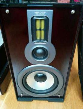
I bought a pair of these this morning from a car boot sale for £10 (should have haggled!). Obviously, I had to look inside. I traced out the crossover, but I seem to have forgotten how to add images here. Anyway, the crossover is pretty much as you would expect. The bass driver has a CR Zobel network across it and is fed via a series inductor, so it relies largely on acoustic roll-off. The dome tweeter is fed by a third order CLC filter but has a 4R7 resistor in series with the tweeter. The leaf tweeter (it's not a ribbon) is fed via a second order CL filter.
They are genuine 4R loudspeakers with quite a mild phase response (<50 degrees). Impedance suggests the reflex box is tuned for 50Hz -3dB (quite ambitious for a small box). I'd leave the crossover well alone - that leaf tweeter is fragile. I may make some acoustic measurements at some point. The box is nice and solid, although I doubt that all that plastic bling on the front does the polar response any favours. Stopping the port to convert it into closed box might be a worthwhile experiment.
They are genuine 4R loudspeakers with quite a mild phase response (<50 degrees). Impedance suggests the reflex box is tuned for 50Hz -3dB (quite ambitious for a small box). I'd leave the crossover well alone - that leaf tweeter is fragile. I may make some acoustic measurements at some point. The box is nice and solid, although I doubt that all that plastic bling on the front does the polar response any favours. Stopping the port to convert it into closed box might be a worthwhile experiment.
It's October and the years is 2021.
14 years now these speakers are running beautifully, even at loud volume.
Remember, speakers work on impedance, not resistance. Therefore, reactance is all that needs to be checked.
Running off an Onkyo 100W amp. TXSR-313
14 years now these speakers are running beautifully, even at loud volume.
Remember, speakers work on impedance, not resistance. Therefore, reactance is all that needs to be checked.
Running off an Onkyo 100W amp. TXSR-313
Hi. I have. Pair of MCD708* and ther is a terminal plate with binding posts on back, plus the front ring/tweeter plate is removable, if careful to protect the cabinet face, though I haven't-yet.
My question is: Anybody here know what value of capacitor is used on the tweeter(I'm assuming it's a cheap NP electrolytic but it's not located st the binding post plate as with many small units)? I want to replace with metal film.
And where are cap & coil located in box so I know where to look?
Thanks . . -Chas
I appreciate that. Surprising-
Since Phillips specifies that tweeter at 8 ohms, 1uf would cross the tweeter pretty high, (even with a padding resistor) unless it's actually a second order filter with a series resistor...🤔
I'll take these MCD708 apart this weekend to see how the stock crossover was implemented.
Thanks.
Since Phillips specifies that tweeter at 8 ohms, 1uf would cross the tweeter pretty high, (even with a padding resistor) unless it's actually a second order filter with a series resistor...🤔
I'll take these MCD708 apart this weekend to see how the stock crossover was implemented.
Thanks.
Last edited:
Okay, I finally opened up both MCD708 pairs (yes, I snagged a second pair locally).
On the first pair there was a crossover pcb (board marked "mcd707") attached to the terminal cup, using a cap and air core inductor, with no power resistors to be seen. I will need to measure the unseen values. On the second pair(serial numbers show them to be later production)
there is no crossover board, only a 3.3uf series cap for the tweeter!
Strange, as the stickers all say "MCD708"., and the drivers are identical.🤔
Anyone else have a pair of the MCD708s, and how are yours equipped?
Indian made Philips speakers had a series capacitor for the tweeter, 4.7 uF /35V, IIRC.
Nothing else.
The ones I have opened did not have stuffing or baffles either.
If they sound good, let them be.
Nothing else.
The ones I have opened did not have stuffing or baffles either.
If they sound good, let them be.
Yeah, the ones with the vinyl cabinets had 5-in woofers run full range and a 4.7 microfarad cap to the tweeter. My model 708 rosewood veneer speakers have a four and a half inch woofer and the low serial numbers have a second order filter to the tweeter using 3.3uf in series, and a 0.2mH choke in shunt. The high serial number ones use the woofer full range and just a 3.3 microfarad to the tweeter.
They all sound fine to my ears, But I may do some careful. A/B comparisons.
It's curious to see the differences between several seemingly identical bookshelf speakers.
I'm going to try biamping one pair with an active crossover, to see what they're really capable of.
Thanks for the info
🐶+🐦=🎶
Stock X/O on right. Modified X/O on left, replaced NPE with a Polycap. Subtle, but noticeable improvement in treble detail. 👍
Last edited:

I've had four sets of these (apparently the amp unit fails often leading to the speakers alone being sold). Only one of them had the PCB crossover and inductor. The others just had the 3.3uF cap on the tweeter. Why four pairs? The first pair had the PCB crossover and sounded pretty good...Okay, I finally opened up both MCD708 pairs (yes, I snagged a second pair locally).
On the first pair there was a crossover pcb (board marked "mcd707") attached to the terminal cup, using a cap and air core inductor, with no power resistors to be seen. I will need to measure the unseen values. On the second pair(serial numbers show them to be later production)
there is no crossover board, only a 3.3uf series cap for the tweeter!
Strange, as the stickers all say "MCD708"., and the drivers are identical.🤔
Anyone else have a pair of the MCD708s, and how are yours equipped?
- Home
- Loudspeakers
- Multi-Way
- Philips MCD-908 Speaker fix