Hi, I'am new here.
My name is Felix and I'am 27 years old.
Five years ago, I started building guitar amps and hifi amps with tubes - just from ordinary layouts, without the ability to understand what I do, maybe a little bit. After the years I get more into it, with reading schematics and building point to point stuff.
I work as an educator in a schoolchild care, so I don't have any vocational connections to electrics and tubes, but I want to learn more about it.
My HiFi rack consists of a Yamaha P2200 Power Amplifier, a Raphael Audio Orthophonic preamplifier, and two DIY
"Statement" speakers
I'am not happy with the preamp, because the small power transformer died.
So I thought it's time to build a preamp, with a phono stage.
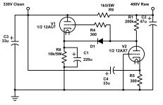
I heard about Thorsten Loeschs RIAA and 6sn7 Line Stage and found a guy (Martin Ruppel) who combined the two of them (PhonoII - so I decided to do it in the same way as Martin.
Martin uses a RGN1064 rectifier tube - I want to go a bit cheaper with a ez81 tube, so I just need a transformer with 6,3V heater windings.
Rectifying 2x300V AC with a EZ81 means 293V DC before the reservoir capacitor - which actually shouldn't be higher value than 50uf.
Now my problem is, what comes after the reservoir capacitor - how many caps, resistors or chokes to achieve the 250V b+ and where can I split the B+ tap for the right channel, where for the left channel.
I thank everyone for your wisdom and advice.
Felix
My name is Felix and I'am 27 years old.
Five years ago, I started building guitar amps and hifi amps with tubes - just from ordinary layouts, without the ability to understand what I do, maybe a little bit. After the years I get more into it, with reading schematics and building point to point stuff.
I work as an educator in a schoolchild care, so I don't have any vocational connections to electrics and tubes, but I want to learn more about it.
My HiFi rack consists of a Yamaha P2200 Power Amplifier, a Raphael Audio Orthophonic preamplifier, and two DIY
"Statement" speakers
I'am not happy with the preamp, because the small power transformer died.
So I thought it's time to build a preamp, with a phono stage.
I heard about Thorsten Loeschs RIAA and 6sn7 Line Stage and found a guy (Martin Ruppel) who combined the two of them (PhonoII - so I decided to do it in the same way as Martin.
Martin uses a RGN1064 rectifier tube - I want to go a bit cheaper with a ez81 tube, so I just need a transformer with 6,3V heater windings.
Rectifying 2x300V AC with a EZ81 means 293V DC before the reservoir capacitor - which actually shouldn't be higher value than 50uf.
Now my problem is, what comes after the reservoir capacitor - how many caps, resistors or chokes to achieve the 250V b+ and where can I split the B+ tap for the right channel, where for the left channel.
I thank everyone for your wisdom and advice.
Felix
It's ohms law mainly. This will help you: PSUD2
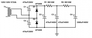
IMHO tube rectification is a waste of electricity. Just use UF5408 and call it a day")
Or do what I do and use a 12V SMPS and a 280V boost converter 150W Inverter Boost Board Transformer DC-AC Converter 12V to 110V 200V 220V 280V 665985430015 | eBay
IMHO tube rectification is a waste of electricity. Just use UF5408 and call it a day
Or do what I do and use a 12V SMPS and a 280V boost converter
150W Inverter Boost Board Transformer DC-AC Converter 12V to 110V 200V 220V 280V 665985430015 | eBayI agree with the general assessment that new HIFI designs/builds should employ SS rectification. However, IF vacuum rectifiers are already on hand, using them in preamps is fine.
UFnnnn diodes are much quieter than their 1nnnn counterparts, but they do produce a bit of switching noise. High PIV Schottky diodes, like this, are switching noise free.
UFnnnn diodes are much quieter than their 1nnnn counterparts, but they do produce a bit of switching noise. High PIV Schottky diodes, like this, are switching noise free.
Based on the voltage value on your schematic
V1, ecc808 consume about 600uA, V2, 7308 about 15mA, V3, 6SN7 about 8mA for the 2 halfs. For 2 channel, you are looking at 2X24mA or 48mA. "If" the output of EZ81 is truly 293V, the resistance needed = (293-250) / .048A or ~900 ohms. It will consume .048 * 43 2W so you will need a 5W+ or so resistor.
V1, ecc808 consume about 600uA, V2, 7308 about 15mA, V3, 6SN7 about 8mA for the 2 halfs. For 2 channel, you are looking at 2X24mA or 48mA. "If" the output of EZ81 is truly 293V, the resistance needed = (293-250) / .048A or ~900 ohms. It will consume .048 * 43 2W so you will need a 5W+ or so resistor.
I agree with the general assessment that new HIFI designs/builds should employ SS rectification. However, IF vacuum rectifiers are already on hand, using them in preamps is fine.
UFnnnn diodes are much quieter than their 1nnnn counterparts, but they do produce a bit of switching noise. High PIV Schottky diodes, like this[\URL], (repl \ with slash) are switching noise free.
Insofar as I can tell, vacuum rectification is basically noise-free, at least from a “switching noise” perspective. It only “suffers” from having a substantially higher VF forward voltage drop. And being relatively expensive. And bulky. But it does also bring slow(er) turn-on to the party. And a nice glittery Big Tube that Glows.
I've long wondered why snubbers (even trivial ones) aren't “standard issue” included in most power supply designs using solid-state rectifiers. Kind of overcomes the buzz, passively. But as long as we're on that, I've also wondered why series MOSFET filtering also isn't de rigueur as well. Particularly cost effective way to downsize all those expensive chokes and decent electrolytics in the PS department.
Just saying,
GoatGuy ✓
But it does also bring slow(er) turn-on to the party.
Directly heated types turn on nearly as quickly as SS diodes. Types with cathode sleeves, in particular damper diodes, are slow starting.
I'am not happy with the preamp, because the small power transformer died.....
Might be easier/cheaper to replace the transformer than to build an extravagant new preamp.
Sorry, I forgot where I was.
It's not "just Ohm's Law", though that is certainly essential.
Aside from Basic Religious Decisions (bottles, 1N4007, chokes), the key thing is to get LOW hum on the B+. Right from a naked rectifier we have hundreds of Volts of ripple, which will wipe-out the millivolt signals.
Assuming R-C filtering, you want to start with raw DC at least 20% higher than your clean DC, to have enough R in your R-C filters to cut hum down without trashcan-size caps. This suggests raw DC near 300V.
BUT if you won't replace your old preamp PT, you probably won't custom-order a PT for this project, so you have to find a stock unit. Many of these will be aimed for 350V-450V.
BTW, the exact value of B+ is not critical! Higher sounds better but heat and cost rise faster than sound quality. We'll take anything near 250V-290V.
A quick stab with 325VAC(CT), bottle rectifier, 33uFd, and 5k (250V/50mA) load gives 400V. Actually this will be 400V/50mA or 8k load. We get like 420V with 17V peak-peak ripple.
We want ripple AT-LEAST 90dB down from signal. Say 1V signal. 0.000,03V or 30uV ripple.
Each stage has at least 1k and 47uFd individual filter, about 30:1, so the main +250V line has to be cleaner than 1mV.
Taking a little liberty, we want to cut 17V to 1mV or 17,000:1, or 84dB from raw DC to the plan you show.
It is practical to take 20dB to 40dB in each R-C stage. 30dB is often a happy goal. 84dB/30dB makes makes 3 R-C stages. 3 R 3 C.
We have 420V and want near 250V (or so). 420V-250V is 170V. 170V/3 is 55.67V.... oh, round it to 50V drop in each resistor. At ~~50mA demand this makes a nice round 1k resistor. Each resistor dissipates 50V^2/1k or 2.5 Watts. These must be 5-Watt rated parts! I would go 10 Watts. Need a lot of air around the whole thing!! (This "preamp" eats more power than an entire Champ guitar amplifier.)
For 30:1 filtering of 100Hz ripple we need an R-C corner near 3.3Hz. Wild try: 47uFd against 1k is 3.4Hz. Because that "90dB" goal is not that great, _I_ would pencil-in 100uFd three times.
But let's ask the computer. PSUD is telling me 258V and 38uV of ripple, about 20X better than goal. Actually, using 33uFd throughout just-hits our 1mV goal. I'd rather be much better. If 33u is cheaper by the 10-pack, double-up to 66u after the first cap. This makes 130uV at the 258V line, which reduced 30:1 at each stage's filter is 4uV at the plate feeds. PSRR of triodes is OTOO 2:1 so 2uV at plates. By contrast, tube hiss is a uV or more at the grid multiplied by the stage gain, so dozens of uV hiss at the plate. These can not be compared directly: you can pick a pure tone far below random noise, OTOH low-level 100Hz is well down the Fletcher-Munson curve so not real audible.
The difference in cost 33u+100u+100u+100u or seven 33u slightly favors the 10-bag of 33uFd (you will find use for the 3 leftover). But the count-on-thumbs knee-jerk over-kill 3x100uF design is not wrong either.
Attachments
Or use a choke input and not have to pisse away 170VDC... 4.5H chokes are 5 dollars CAD from a1parts.ca
I personally have a preference for large caps and small resistors since it's less wasteful. See this schematic for my power amplifiers. Less than 1V ripple for the push pull output stages.
And for my phono preamp I use a "Janus" regulator. One per channel.
I personally have a preference for large caps and small resistors since it's less wasteful. See this schematic for my power amplifiers. Less than 1V ripple for the push pull output stages.
And for my phono preamp I use a "Janus" regulator. One per channel.
Attachments
Hi Folks,
thank you all! It's not that easy theme for me, because I want to do it right, but I don't have any notion how to build a power supply, that fits for the different rectifiers as well as for the tube phono and line stage
The easiest way, would probably be a diode rectifier with big filter caps and maybe a regulator.
I like the idea of using a big rectifier tube like the 5Z3C (russian 5u4g), but I need help with the schematic for the PSU and the right transformer choice.
So here is my transformer candidate:
Ampdesign
Secondaries:
280V - 0 - 280V 0,25A
2x 6,3V, 1,6A
2x 8,5V, 0,7A
5V, 3A
I need the PSU for exact this schematic:

I know about my lack of PSU knowledge, and I'am sorry for that. I need a few hours of reading and understanding whats going on in a PSU (ripple etc.) Maybe I can find a good book in my mother language- but maybe someone have mercy with me and a good schematic.
So that no boredom arises a picture taken from my sofa
thank you all! It's not that easy theme for me, because I want to do it right, but I don't have any notion how to build a power supply, that fits for the different rectifiers as well as for the tube phono and line stage
The easiest way, would probably be a diode rectifier with big filter caps and maybe a regulator.
I like the idea of using a big rectifier tube like the 5Z3C (russian 5u4g), but I need help with the schematic for the PSU and the right transformer choice.
So here is my transformer candidate:
Ampdesign
Secondaries:
280V - 0 - 280V 0,25A
2x 6,3V, 1,6A
2x 8,5V, 0,7A
5V, 3A
I need the PSU for exact this schematic:
I know about my lack of PSU knowledge, and I'am sorry for that. I need a few hours of reading and understanding whats going on in a PSU (ripple etc.) Maybe I can find a good book in my mother language- but maybe someone have mercy with me and a good schematic.
So that no boredom arises a picture taken from my sofa
An externally hosted image should be here but it was not working when we last tested it.
Using a 12V SMPS and a boost converter would be simpler, cheaper and more than likely work better IMHO. Also 5Z3C is overkill for this. If I were to use a vacuum rectifier for your circuit, I'd use a Chinese 6Z4. 4 x ShuGuang 6Z4 New Tested Vacuum Tube For Tube Amplifier Psvane | eBay
Or use a choke input and not have to pisse away 170VDC... 4.5H chokes are 5 dollars CAD from a1parts.ca...
You may have missed my point about "transformers you can find". Confirmed by Sunwontrise's pick of a 280VAC part which wants to give 400VDC.
And no $5 chokes near my woods. (That Coil-58 is 4.5H but at what mA?)
Now the choice to use the over-size 5U4-type rectifier. (A 5Y3 would be ample.) This is easily figured on 5U4 data, attached. He'll have 350VDC and wants nearer 250VDC (or have to check a lot of parts for twice the dissipation); and cleaner than raw rectifier into any size first cap.
> a good schematic
Don't make us draw more! The woods are FULL of power supply schematics! Schematics don't rely much on language.
If totally lost, look at the Champ I mentioned: Champ AA764. Notice how it gets raw DC from the rectifier on the first capacitor. Then it runs through several R-C filters to get clean-enough for guitar preamp. You'll do the same idea, skipping the "+360V" tap for the 6V6 stage, using smaller resistors in more R-C filter stages, to get clean power for your phono amp.
Attachments
I don't think I missed the point. A choke input won't yield 400VDC from a 280VAC coil, more like 250V (using Si diodes) or so. If the OP is interested, I can send them a pair of those coils for about 15 Euro.
http://www.hammondmfg.com/pdf/5c007.pdf
Coil-58 is good for about 50mA, the less current, the higher inductance and vice versa.
A 6Z4 rectifier is not only easier since it's indirectly heated and runs from the common 6v3 heater windings, but it's also only 3 bucks. By all means though, if the OP wants to waste money that's their decision.
Last edited:
- Status
- This old topic is closed. If you want to reopen this topic, contact a moderator using the "Report Post" button.
- Home
- Amplifiers
- Tubes / Valves
- Phono and Line Preamp build - PSU question