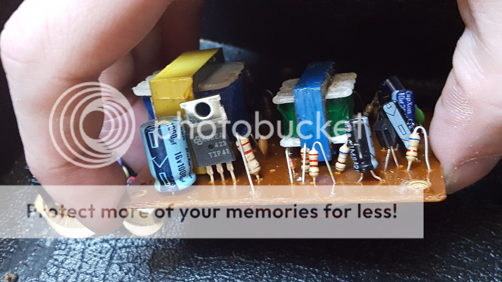
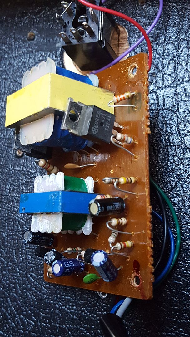
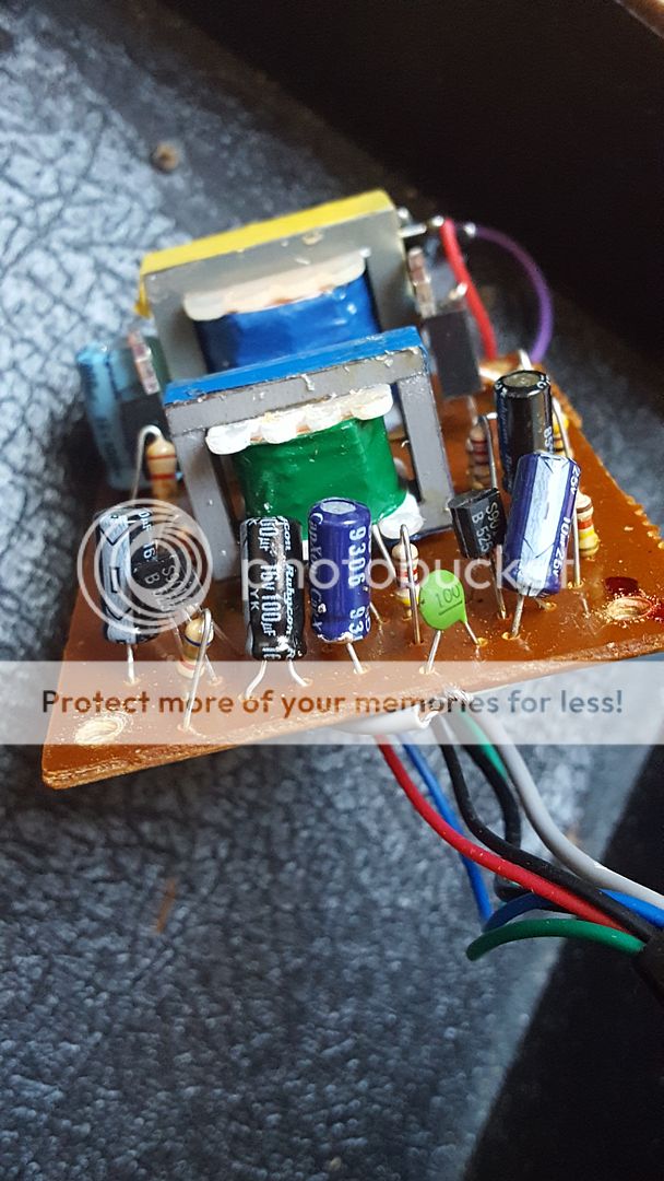
Hi, new to this forum and looking for advice on a repair.
My cousin put a line 6 Pod on full whack thru my pignose, also cranked full. It made a whimper then died.
I tried it with my guitar direct into amp and it's now outputting at very low volume which fluctuates. Does anyone know what has blown? I love this amp and hope it's not a goner!
Thanks in advance.
Amazon tells me its a little mains/battery amp so more than likely it uses some kind of 'chip amp'.
If you can come up with circuit details then that would be great, if not then its a case of having a look inside to see what technology it uses.
If you can come up with circuit details then that would be great, if not then its a case of having a look inside to see what technology it uses.
There are variations on the venerable Pignose, but this is typical:
http://bmamps.com/Schematics/Pignose/Pignosemodel 7-100b.jpg
The whole thing is four transistors and a bunch of passives.
http://bmamps.com/Schematics/Pignose/Pignosemodel 7-100b.jpg
The whole thing is four transistors and a bunch of passives.
Well speaker works, but it's about half as loud as it was, so my guess is the power amp has blown. There's not much info around on the net reg repairs. Do you think it's possible to have fried a transistor by putting a loud preamp at the front of the circuit?
I must add I'm fairly green when it comes to electronics
Thanks.
I must add I'm fairly green when it comes to electronics
Thanks.
Yes, the input transistor could have become destroyed. Replacement should not be too difficult, one just needs to obtain a suitable replacement part, i guess this is a Germanium transistor. When you are fixing it, please add a 1N4148 anti-parallel to input diode of this transistor in order to prevent this kind of damage for the future.
Wow, that's very old school design. Wasn't expecting that tbh. Germaniums ? do we still use those 😀
You need to do some very basic checks with a multimeter.
1/ With the unit OFF, measure the resistance of that 1ohm (marked 1E) resistor. Is it OK ?
2/ With the unit ON, touch and compare temperatures of the two 2SB324H transistors. Both should be cool.
3/ As confirmation of the above two steps now measure the DC voltage ACROSS that 1ohm. What have you got ? I would imagine you would see only a few millivolts DC.
4/ Connect the RED meter lead to ground.
5/ Measure and record the DC voltage on the three legs of the 2SB172 input transistor. I would guess the collector would be around 4 to 6 volts depending on supply voltage.
Appreciate the help, is this the transistor you think could be damaged? 2SB172 Transistor Germanium Case TO1 Make Panasonic | eBay
There are many variations around the basic circuit, that amp has been made for almost 50 years.
Yes, originals were germanium, as in the circuit posted above, but later ones were silicon.
Random placing a transistor there when you haven´t even checked what the originl is is a BAD IDEA 🙂
Please open the amp´s little chassis , expose the PCB, take a couple sharp well illuminated pictures and post them here.
Read labels on each transistor and post them too, sowe can suggest some voltage measurements and possible replacemants.
Your amplifier *might* have germanium transistors as shown in the schematic or not.
Please open the amp´s little chassis , expose the PCB, take a couple sharp well illuminated pictures and post them here.
That is what you need to do really. Lets be sure what you have first.
I'll set up a photo bucket account so I can add pics but the readings on the transistors are 2x 's9014b 525' , and 2 larger ones with parallel legs with 'Korea 423 tip41'
Silicon 🙂
The TIP41 is a common device, the 9014 is a general purpose NPN small signal type.
OK, so the tests I listed above are all valid except that now it will be the black meter lead that connects to ground rather than red. The 1 ohm is now a 2.2 ohm and is that large one next to the TIP 41 in the first picture.
I'll be honest, I've no idea how to use a multimeter. I'm sure I've got one tho, I'll dig it out and have a go, thanks.
OK 🙂
The cost of all the transistors is minimal just to replace all of them. If you are in the UK then even at Maplin prices it would only be around £3 to £4 (which is £2 to £3 more than it should be but that's what you pay for high street store convenience I guess).
Lets see what the tests show up first though.
I wouldn't like to say at this stage tbh. My initial thoughts are that it seems 'unlikely' and yet there is little else in there.
As always, fault finding has to be logical and that begins with basic tests and voltage readings. Otherwise its all guesswork.
As always, fault finding has to be logical and that begins with basic tests and voltage readings. Otherwise its all guesswork.
yeah, I linked the schematic more to show the basic simplicity iof the circuit rather than specific transistors. These little amps have indeed been around for decades, and to me are worth the price just for the knob on the volume control (which looks like a pig's nose).
There is a logical fallacy titled something like "post hoc ergo propter hoc". meaning roughly "it came after this so must be because of this". Point being, that it may be coincidence this occurs right after some event like too hot a signal. Just disassembling the thing has potential to knock something askew. The wiring to and from the volume pot, the wires connecting to the board. Those board mounted transformers, any chance a wire broke off one of them?
It is indeed cheap to just replace all four transistors, but I wouldn;t until I had reason to think a transistor was the actual problem. You could have a cap with a broken lead, and all the transistors in the world won;t help that.
1) so it is Silicon after all
2) Small transistors are 2SB525, large ones are TIP41, all other codes are date and factory codes, don´t mean much if at all.
3) your circuit should be close to this:
mind you, it has errors, read this thread in full:
http://www.diyaudio.com/forums/solid-state/229767-pignose-conversion.html
worst error is that he measured resistance values still soldered to the board, better ones are the *indicated* (those between () ) values, except the emitter resistor which is some 2 ohms (what you have) and not what he read as 2k7.
This is another Silicon Version:
compare these to what you have.
EDIT: the bottom one is way better, with the only difference on the output transistors biasing, it uses higher resistive values and an unknown thermistor while yours should look like the top one, with a Si diode.
But if you caný use a multimrter nor troubleshoot, better ask some Tech friend to help you ... or straight send it to a Tech shop.
Show him these suggestions if necessary, a modern Tech never saw something like this, unless he´s >60 y.o.
It´s basically the power amp in an OLD transistor radio.

notice the metallic case germanium transistors, it also has 2 transformers: driver and output.
2) Small transistors are 2SB525, large ones are TIP41, all other codes are date and factory codes, don´t mean much if at all.
3) your circuit should be close to this:
An externally hosted image should be here but it was not working when we last tested it.
mind you, it has errors, read this thread in full:
http://www.diyaudio.com/forums/solid-state/229767-pignose-conversion.html
worst error is that he measured resistance values still soldered to the board, better ones are the *indicated* (those between () ) values, except the emitter resistor which is some 2 ohms (what you have) and not what he read as 2k7.
This is another Silicon Version:
An externally hosted image should be here but it was not working when we last tested it.
compare these to what you have.
EDIT: the bottom one is way better, with the only difference on the output transistors biasing, it uses higher resistive values and an unknown thermistor while yours should look like the top one, with a Si diode.
But if you caný use a multimrter nor troubleshoot, better ask some Tech friend to help you ... or straight send it to a Tech shop.
Show him these suggestions if necessary, a modern Tech never saw something like this, unless he´s >60 y.o.
It´s basically the power amp in an OLD transistor radio.
An externally hosted image should be here but it was not working when we last tested it.

notice the metallic case germanium transistors, it also has 2 transformers: driver and output.
Last edited:
- Status
- Not open for further replies.
- Home
- Live Sound
- Instruments and Amps
- Pignose 7-100 repair


