Hi everyone,
I’m trying to repair Pioneer D9601 mono amp, someone tried to repair it before me, but they just couldn’t get it to work.
I measured resistance of 4227 output transistors, gate and source is 4.74 for low side and other resistors show 4.64, some resistors were clearly changed before, but they seem to be working. All of them are charging as far as I checked no short.
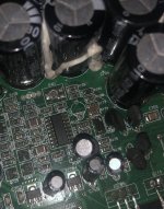
Up on opening the case, I noticed one resistor is missing and was changed to two resistors and one capacitor is missing as well. I tried to find values of resistor and capacitor, but no luck.
I will attach some pictures, perhaps someone knows what resistor and capacitor I should use.
The amp turns on, but goes to protection mode, red led lights up.
Any help appreciated, thanks.
I’m trying to repair Pioneer D9601 mono amp, someone tried to repair it before me, but they just couldn’t get it to work.
I measured resistance of 4227 output transistors, gate and source is 4.74 for low side and other resistors show 4.64, some resistors were clearly changed before, but they seem to be working. All of them are charging as far as I checked no short.
Up on opening the case, I noticed one resistor is missing and was changed to two resistors and one capacitor is missing as well. I tried to find values of resistor and capacitor, but no luck.
I will attach some pictures, perhaps someone knows what resistor and capacitor I should use.
The amp turns on, but goes to protection mode, red led lights up.
Any help appreciated, thanks.
Attachments

The two series resistors appear to be one of the 4227 gate resistors. Measure the gate resistors for the other 4227s and use the same value.
What is the part number marked on the IC in the photo?
What is the part number marked on the IC in the photo?
I found pcb layout for D9601, I will share so others can use it as well.
Could you please take a look at it and confirm capacitor and resistor values?
I believe C151 is 220uF 25V capacitor(??)
and R179 is 10K ohm resistor(??)


picture quality is terrible, not sure how to share it at full resolution, I'll add links below, if it's unreadable let me know, I will edit with photoshop.
scale_2400
scale_2400
Could you please take a look at it and confirm capacitor and resistor values?
I believe C151 is 220uF 25V capacitor(??)
and R179 is 10K ohm resistor(??)
picture quality is terrible, not sure how to share it at full resolution, I'll add links below, if it's unreadable let me know, I will edit with photoshop.
scale_2400
scale_2400

Back again with no luck…
Just changed resistor and capacitor, hooked up on battery instead of weak PSU, protection red led comes up and blinks every 5-7 seconds, any advice?
Thanks.
Just changed resistor and capacitor, hooked up on battery instead of weak PSU, protection red led comes up and blinks every 5-7 seconds, any advice?
Thanks.
Do you have an oscilloscope?
Have you tried connecting a subwoofer to the amp to see if it pops/clicks when you try to power the amp up?
Have you tried connecting a subwoofer to the amp to see if it pops/clicks when you try to power the amp up?
Hi Perry,
I have an oscilloscope, but only ever used is to adjust gain… weird thing happened red led blinked and blue light turned on, I turned off the amp to set up cables properly (to test it properly) and now red led flashes again.
It goes like this red led blinks once (barely visible) then blinks red led full bright and keeps cycling like that.
If you go back to the connections when it turned blue, will it again go to blue?
Have you tried connecting a subwoofer to the amp to see if it pops/clicks when you try to power the amp up?
Have you tried connecting a subwoofer to the amp to see if it pops/clicks when you try to power the amp up?
I haven’t I’m working at home, I have to remove car seat to access my other amp and sub cables…
No blue light, just red protection keeps flashing, battery shows 13 volts.
Can o-scope help instead of subwoofer?
when I hook up o-scope on speaker connection, everytime led blinks o-scope line jumps up.
No blue light, just red protection keeps flashing, battery shows 13 volts.
Can o-scope help instead of subwoofer?
when I hook up o-scope on speaker connection, everytime led blinks o-scope line jumps up.
What parts were replaced by the previous tech?
Sometimes it's difficult to see a startup pulse with a scope. How far (voltage) does it jump? 0.1v is different than 40v.
Sometimes it's difficult to see a startup pulse with a scope. How far (voltage) does it jump? 0.1v is different than 40v.
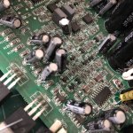
So it came with missing C151 capacitor (changed), 2 different value resistors R179 (swapped to correct one).
Seems like all 6x IRFB4227 mosfets were changed.
Also PCB is very dirty not sure where he kept it, even heatsinks were not included, I guess he just gave up on it.
Is it normal to read - voltage for speaker terminals? positive to positive and neg. to neg. gives - voltage.
I removed that solder blob, still red protection blinking.
Attachments


The solder was not doing anything bad but it didn't hurt to remove it.
Do all of the audio FETs read ~5k from pin 1 to pin 3 (check all individually)?
Do all of the audio FETs read ~5k from pin 1 to pin 3 (check all individually)?
Find Q729 and bridge it from emitter to collector. Remove R161 (connected to Q104). Will the amp power up (blue LED)?
It won't produce audio.
Do you still see a pulse on the output with Q729 bridged?
It won't produce audio.
Do you still see a pulse on the output with Q729 bridged?
The image is for a different IC but the pin names/functions are the same as the 2092 (datasheet attached). Measure the resistance for the 6 tests shown (matching pin names/functions, not the pin numbers). What's the lowest resistance reading you get?
Attachments

- Home
- General Interest
- Car Audio
- Pioneer D9601 repair