I have been having a lot of fun with my new 3d printer. I want to build a dipole planar CBT to try to improve over my previous full range dipole CBT https://www.diyaudio.com/community/threads/cbt-dipole-with-sb65wbac25-4.353962/
The area I'm focusing on now is the tweeter. There is no supply of lots of BG Neo3W which is the version with excellent dipole response available so I have had to make do with the GRS PT2522. It is, however, a clone of the Neo3PDR so same problems as the PDR: the horizontal off axis response at 6 khz - 9 khz is not ideal. Pretty much why the Aino Gradient 83 mounts the neo3PDR tweeter sideways. But that compromises high end off axis response so I want to avoid that.
So, I have been experimenting with waveguides. But with a solid waveguide we get a large dipole peak below the horn loading frequency so unless they are LARGE enough to cover the whole area they usually make things worse rather than better.
This gave me the idea to make the waveguides hollow. Originally to have a big enough waveguide and use the slot holes for the woofers like a synergy horn. But after experimenting more I found that these holes could help mitigate the dipole peak.
And it seems to work pretty well! It does mess upp the response slightly from 1.5 khz to 5 khz but in return it completely cleans up the response from 5 khz and upwards. Given the benefits I think it would be a trade I'd be willing to make.
I'll have to experiment with more / less slots and if I should increase or reduce the wg size.
Attachments


Have you tried making the edges wrap around to meet each other like the sides make part of a toroid?
Looks ugly and is a waste of time and money ... better buy used KEF Q150 or Q350 and tweak to taste!
https://www-hifialex-de.translate.goog/?_x_tr_sl=de&_x_tr_tl=en&_x_tr_hl=de&_x_tr_pto=wapp
https://www.hifialex.de/wp-content/uploads/2018/01/Q350_HT_0-90_50cm_5ms.png
https://www-hifialex-de.translate.goog/?_x_tr_sl=de&_x_tr_tl=en&_x_tr_hl=de&_x_tr_pto=wapp
https://www.hifialex.de/wp-content/uploads/2018/01/Q350_HT_0-90_50cm_5ms.png
Not yet, but I will.Have you tried making the edges wrap around to meet each other like the sides make part of a toroid?
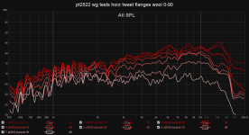
Only I have tried so far is the measurements in the main post and I have tried to add some wool carpet in between the sides as in the image but with the horizontal wg. It has previously shown good results but here it measured worse than no wool in both the naked and the horizontal wg configuration.
Attachments


Looks ugly and is a waste of time and money ... better buy used KEF Q150 or Q350 and tweak to taste!
https://www-hifialex-de.translate.goog/?_x_tr_sl=de&_x_tr_tl=en&_x_tr_hl=de&_x_tr_pto=wapp
https://www.hifialex.de/wp-content/uploads/2018/01/Q350_HT_0-90_50cm_5ms.png
Those drivers are not dipoles. I can make the response more uniform if I design for a cardioid response. In that case then I would get such a driver or something similar.
But my listening experiments have shown that I strongly prefer a dipole radiation pattern over a cardioid so that is what I want to build. And planars like the PT2522 while not as uniform in the response as the KEF is pretty much one of the best dipole drivers on the market since the design is symmetric front to back.
I'll have to wait until next weekend until I get access to my measurmenet equipment so I'll have to print some different configs until then:
An observation I found is that that the waveguide seems to control directivity more narrowly than a dipole so I want to test a more shallow waveguide and see if the integration is better. The original wg was 2.5 cm deep, I want to try 1.75 cm depth.
I also want to see if adding more slots would reduce the impact on the lower frequency range.
And when we are at it why not test a cheese configuration instead of slots? 🧀
And test to extend the sides by increasing edge roundover. To make it easier to print there will still be a 1cm gap so I'll have to fill it in with tape and some foamcore board when I measure.
Attachments

The Aurum Cantus AST2560 is a much better tweeter as a dipole and does not have the response problems of the B&G/GRS unit. Just unscrew its mounting faceplate and you will get a small and compact dipole tweeter that can be crossed over around 2.2kHz even without any baffle around it.
I used the GRS Neo3 clone in a project last year. After it was demoed at a DIY event I dismantled it and threw away the tweeters. They are not very good IMHO. I would not bother trying to "fix" their flaws. Just move on to something better.
I used the GRS Neo3 clone in a project last year. After it was demoed at a DIY event I dismantled it and threw away the tweeters. They are not very good IMHO. I would not bother trying to "fix" their flaws. Just move on to something better.
The Aurum Cantus AST2560 is a much better tweeter as a dipole and does not have the response problems of the B&G/GRS unit. Just unscrew its mounting faceplate and you will get a small and compact dipole tweeter that can be crossed over around 2.2kHz even without any baffle around it.
I used the GRS Neo3 clone in a project last year. After it was demoed at a DIY event I dismantled it and threw away the tweeters. They are not very good IMHO. I would not bother trying to "fix" their flaws. Just move on to something better.
That is a valid point. I agree that the PT2522 is not the best planar tweeter but I believe it ticks the box of good enough to be usable given my extra set of constraints:
- Reasonable price such that I can get have 150 cm lines (17x PT2522) for each speaker. The PT2522 price is managable but the AST2560 would be 4x as expensive which is a lot.
- Reputable consistency of the manifacturer. Since I'm buying so many drivers I didn't want to have to throw away lots of drivers just to find some decent ones. And I've tested other GRS planars and they had great consistency.
- Since the drivers are quite expensive, if my speaker plans don't pan out I want the drivers to be resellable. The PT2522 being BG Neo3 clones are quite common and would probably be easy to sell. A similar and slightly better driver for my use-case would be the Radian LT2 but I'd have to destructively remove the rear chambers making them a lot harder to resell. The LT2 is also not as common as Neo3 clones so would be a even harder to sell a large quantity.
Because of above reasons I bought a box of 20 PT2522 drivers a while ago to test full scale for a single speaker. So it's kind of sunk cost fallacy where I'm invested in improving them rather than selling them off and buying another driver. It is also pretty fun to play around with unconventional waveuides on the 3d printer 😀
Also, lets say I did switch to Radian LT2 drivers. Then I'd also have to double the expected crossover frequency from ~ 1khz to 2khz since the LT2 doesn't handle the low end as well as the PT2522. So I guess in the end there is no free lunch 🙂
Last edited:
I have:
Empty with no wg or any horizontal wg stuff at all then the ones in the image:
Original = the original wg. 9.5 cm wide excluding edge roundover, 6cm deep and 1.5 cm edge roundover.
Shallow = 9.5 cm wide excluding roundover, 4.5 cm deep, 1.5 cm edge roundover.
Row 1: original, original with 3 slots
Row 2: shallow, whallow with 3 slots, shallow with cheesed slots.
Original as a base case
Row 3: shallow without flanges, only flanges and minimal roundover, only mid flange.
Row 4: shallow with minimal edge roundover.
Attachments


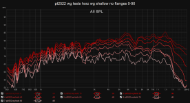
Shallow waveguides:
1. shallow
2. shallow with 3 slots
3. shallow with cheese holes
4. shallow with no flanges
5. shallow with minimal roundover
1. shallow
2. shallow with 3 slots
3. shallow with cheese holes
4. shallow with no flanges
5. shallow with minimal roundover
Attachments
-
 pt2522 wg tests horz wg shallow no flanges 0-90.png67.8 KB · Views: 94
 -
 pt2522 wg tests horz wg shallow cheese 0-90.png68 KB · Views: 89
 -
 pt2522 wg tests horz wg shallow 3 slot 0-90.png67.2 KB · Views: 84
 -
 pt2522 wg tests horz wg shallow 0-90.png65.8 KB · Views: 85
 -
 pt2522 wg tests horz wg shallow minmal edge roundover 0-90.png67.9 KB · Views: 81
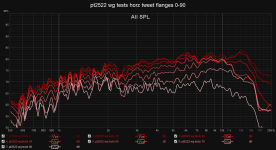
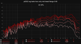
Conclusion:
The shallow waveguides seems to match the dipole dispersion better than the steeper original. Also, the 3 slot and cheese holes seems to make everything worse. I was also was supprised by how much just the mid flange improved things.
All in all I think the best is probably just the flanges with the minimal roundover. A close second is only the mid flange and third the shallow wg with minimal edge roundover. I will probably test some more combinations around those.
Last edited:
I also wanted to try to add some wool carpet to the sides of the minimal roundover. And it did improve the response slightly between 5-20 khz. This looks to be the best combination so far.
Attachments


Random thoughts:
1. If you dig through my post history, I have a thread where I measured what happens when you mask off part of the diaphragm. It's possible to mask off quite a bit, and the tweeter still works. I think the reason for this is because the felt on the edges of the tweeter acts as a acoustic low pass filter. So even if you delay the radiation (by masking off part of the diaphragm), you still get a well behaved response.
2. Bose has a patent on perforated acoustic waveguides. It's worth a look.
3. You can sim planar waveguides in ATH now. The NEO3 is a really good candidate for waveguides, due to it's perfectly flat wavefront. You basically get an ideal wavefront shape without having to deal with a compression chamber.
Fun project!
1. I have peeked at your masking of the tweeter yes. In my other experiments I usually covered the tweeter such that only the inner two holes are exposed and it improved the response somewhat. It was not, however, by itself enough to "fix" the problem of the PDR tweeters where the outer holes don't radiate as much. It worked best on the Neo3W or GR Neo3 which both have 5 rows of magnets instead of just 3. Tomorrow I'm planning to test doing just that but with the added mid flange.
I also have a freshly printed minimal edge roundovers with a mid flange which is 5 cm high instead of 2.5 cm. Not sure if it will be better but will be interesting to see how it differs from the 2.5 cm high flange.
2 & 3. Cool, I'll have to take a look!
I also have a freshly printed minimal edge roundovers with a mid flange which is 5 cm high instead of 2.5 cm. Not sure if it will be better but will be interesting to see how it differs from the 2.5 cm high flange.
2 & 3. Cool, I'll have to take a look!
Attachments

A 5 cm high mid flange seems to perform slightly worse than the more modest 2.5 cm flange:
I remeasured the 2.5cm flange to make sure the comparison is fair.
I remeasured the 2.5cm flange to make sure the comparison is fair.
Attachments


This is one of the best uses of a 3D printer I've seen in awhile. Nice work!
Since the 2.5 cm middle flange performed better I guess I'll have to test going down to a smaller flange, say 1.5 cm. Also I want to test to remove the mini roundovers around the tweeter holes and see if they actually help or are redundant (or maybe even make things worse).
I'll stock up on some more test prints but I'll have to wait until next monday until I have time to measure them.
I'll stock up on some more test prints but I'll have to wait until next monday until I have time to measure them.
- Home
- Loudspeakers
- Multi-Way
- Porous dipole waveguide experiments